
One of the simplest and most classic DACs is the R-2R ladder, but today there are more complex objects with optimization in the signal reconstruction. Below is shown a 3bit R-2R ladder DAC.

Vout= -1/2*B1*Vref – (1/4)*B1*Vref- (1/8)*B1*Vref
If the 3bit string is D and Vref is equal to the logical voltage of 3.3V
Vout= (3.3*D)/2^3
The typical output characteristic is shown in the following figure.
Compared to the weighted resistor DAC, the R-2R scale DAC has the advantage of using only two resistive values. Therefore, it is more easily achievable with integrated circuit technology.
DAC on STM32 platform
Many of the STM32 microcontrollers have on board at least one DAC (generally 12 bit) with the possibility of buffering the output signal (with internal operational amplifier OP-AMP). The use of the DAC finds various applications, for example, it can be used to reconstruct a sampled signal or to generate any waveform (sine wave, square wave, sawtooth, etc.), to generate a reference voltage (for example for a digital comparator).
The DAC peripheral can be controlled in two ways:
- Manually
- Using a Data Memory Access (DMA) with a trigger source (can be an internal timer or external source).
DAC in manual mode
In this modality we can drive DAC to on/off a LED, to generate a reference voltage, etc. We will use a NUCLEO STM32L053R8 board to show as configure DAC with STCube. This NUCLEO has available a DAC with only one channel (in general every DAC has one or more channels) with resolution up to 12bit with a maximum bus speed of 32 MHz and a maximum sampling rate of 4 Msps. First, let’s see how to initialize the peripherals using STCube Tool:
Configuration of DAC in manual mode
DAC Initialization
- Select DAC with following path: “Pinout & Configuration”-> Analog -> DAC. Select the Output 1 (OUT1 Configuration):
- In Configuration->Parameter Setting select Output Buffer= Enable and Trigger = None
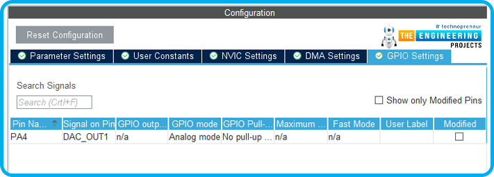
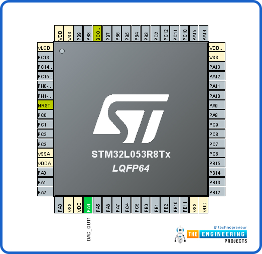
- The GPIO PA4 is associated to DAC Output1. PA4 has been configurated in Analog Mode, No Pull-Up and No Pull-Down.
System Reset and Clock Control (RCC) Initialization
- Select RCC with following path: “Pinout & Configuration”-> System Core -> RCC. “High Speed Clock” (HSE) and “Low Speed Clock” (LSE) select for both “Crystal/Ceramic Resonator”.

Diving into the initialization code
At this point, let’s look at the generated code:
- In “Private variables” we find DAC_HandleTypeDef hdac, it is an instance to C struct that need to manipulate the DAC peripheral:
typedef struct
{
DAC_TypeDef *Instance; /*!< Register base address */
__IO HAL_DAC_StateTypeDef State; /*!< DAC communication state */
HAL_LockTypeDefLock; /*!< DAC locking object */
DMA_HandleTypeDef *DMA_Handle1; /*!< Pointer DMA handler for channel 1 */
#if defined (DAC_CHANNEL2_SUPPORT)
DMA_HandleTypeDef *DMA_Handle2; /*!< Pointer DMA handler for channel 2 */
#endif
__IO uint32_t ErrorCode; /*!< DAC Error code
}DAC_HandleTypeDef;
- In “Private function prototypes” the function prototype used to initialize and configure the peripherals:
/* Private function prototypes ———————————————–*/
void SystemClock_Config(void);
static void MX_GPIO_Init(void);
static void MX_DAC_Init(void);
/* USER CODE BEGIN PFP */
- Where we find the initialization select in STCube Tool.
Driving DAC to generate a reference voltage
Now, before writing our application, let’s see what functions the HAL library makes available to handle the DAC.
- HAL_DAC_Start(DAC_HandleTypeDef* hdac, uint32_t Channel): need to enable DAC and start conversion of channel.
- “hdac” is a pointer to DAC structure
- “Channel” is the selected DAC channel
- HAL_DAC_Stop(DAC_HandleTypeDef* hdac, uint32_t Channel): need to disable DAC and start the conversion of the channel.
- “hdac” is a pointer to DAC structure
- “Channel” is the selected DAC channel
- HAL_DAC_SetValue(DAC_HandleTypeDef* hdac, uint32_t Channel, uint32_t Alignment, uint32_t Data): is used to set in DAC channel register the value passed.
- “hdac” is pointer to DAC structure
- “Channel” is the selected DAC channel
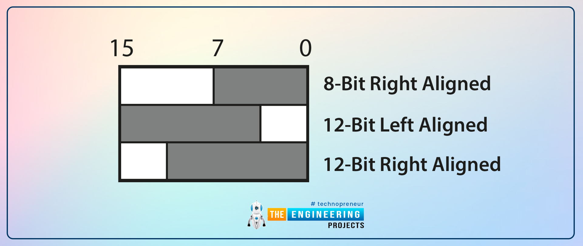
- “Alignment” needs to select the data alignment; we can select three configurations, because the DAC wants the data in three integer formats:
- “DAC_ALIGN_8B_R” to configure 8bit right data alignment;
- “DAC_ALIGN_12B_L” to configure 12bit left data alignment;
- “DAC_ALIGN_12B_R” to configure 12bit left data alignment.
- “Data” is the data loaded in the DAC register.
The voltage output will be:
Vout,DAC = (Vref*data)/2^nb
where nb is a resolution (in our case 12bit), Vref is voltage reference (in our case 2 Volt) and the passed data.
So, to set DAC output to 1 Volt data must be 2047 (in Hexadecimal 0x7FF) so we call the function this way:
HAL_DAC_SetValue(&hdac, DAC_CHANNEL_1, DAC_ALIGN_12B_R, 0x7FF);
To set the output voltage to 3.3 Volt we call function in this way:
HAL_DAC_SetValue(&hdac, DAC_CHANNEL_1, DAC_ALIGN_12B_R, 0xFFF);
To verify that change the value in our main we write the following code and then we check the output connecting it to the oscilloscope probe.
int main(void)
{
HAL_Init();
SystemClock_Config();
MX_GPIO_Init();
MX_DAC_Init();
while (1)
{
/* USER CODE END WHILE */
HAL_DAC_Start(&hdac, DAC_CHANNEL_1);
HAL_DAC_SetValue(&hdac, DAC_CHANNEL_1, DAC_ALIGN_12B_R, 0x7FF);
HAL_Delay(1000);
HAL_DAC_Stop(&hdac, DAC_CHANNEL_1);
HAL_Delay(1000);
HAL_DAC_Start(&hdac, DAC_CHANNEL_1);
HAL_DAC_SetValue(&hdac, DAC_CHANNEL_1, DAC_ALIGN_12B_R, 0x7FF);
HAL_Delay(1000);
HAL_DAC_Stop(&hdac, DAC_CHANNEL_1);
HAL_Delay(1000); /* USER CODE BEGIN 3 */
}
/* USER CODE END 3 */
}
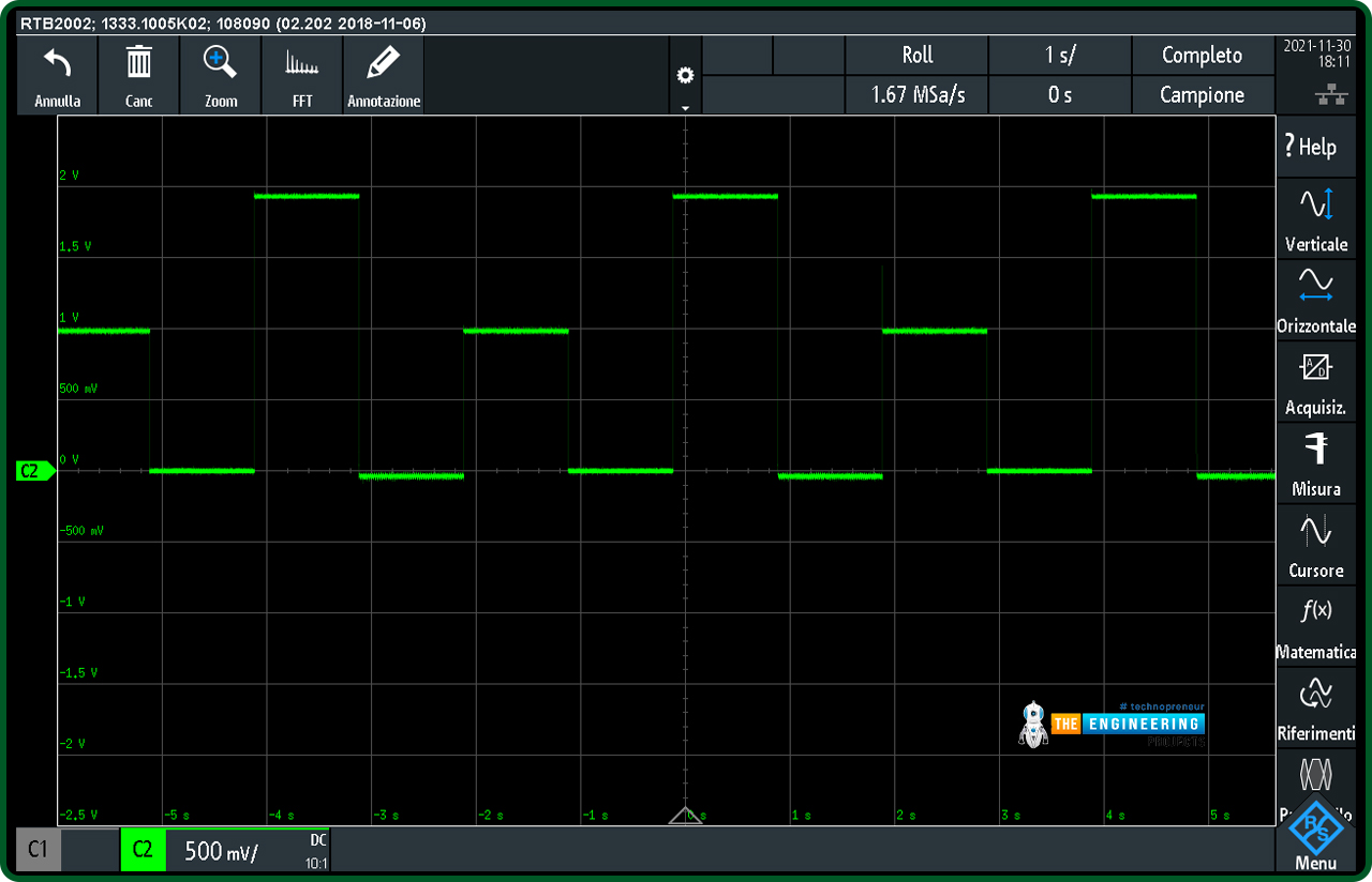
We expect the output voltage to change every second by repeating the following sequence: 1V – 0V – 2V – floating (as shown in the figure below)
Using DAC in Data Memory Access (DMA) mode with a Timer
In this modality we can drive DAC to on/off a LED, to generate a reference voltage, etc. We will use a NUCLEO STM32L053R8 board to show as configure DAC with STCube. This NUCLEO has available a DAC with only one channel (in general every DAC has one or more channels) with resolution up to 12bit with a maximum bus speed of 32 MHz and a maximum sampling rate of 4 Msps. First, let’s see how to initialize the peripherals using STCube Tool:
Configuration DAC in DMA mode
- DAC Configuration
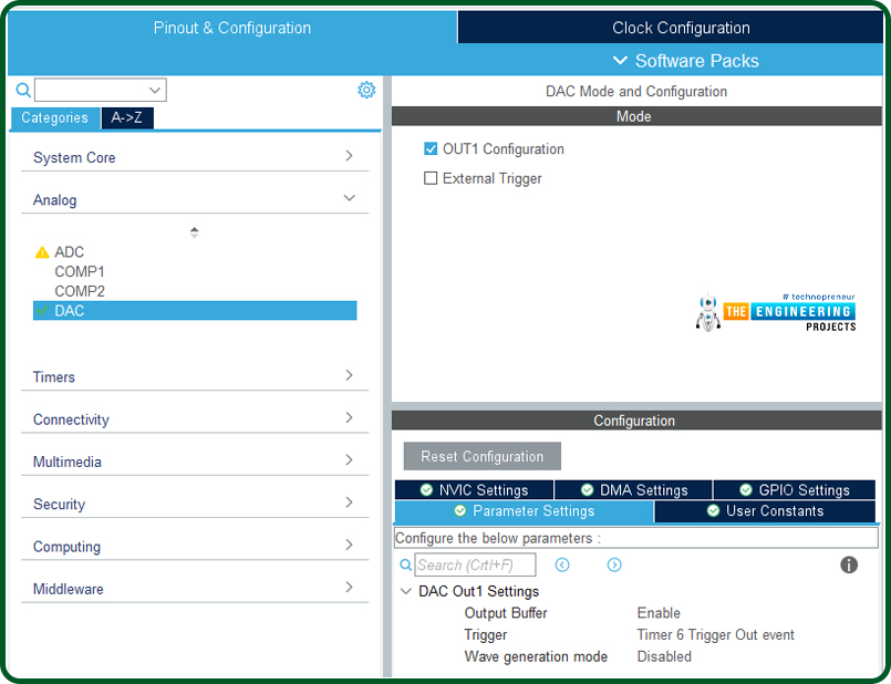
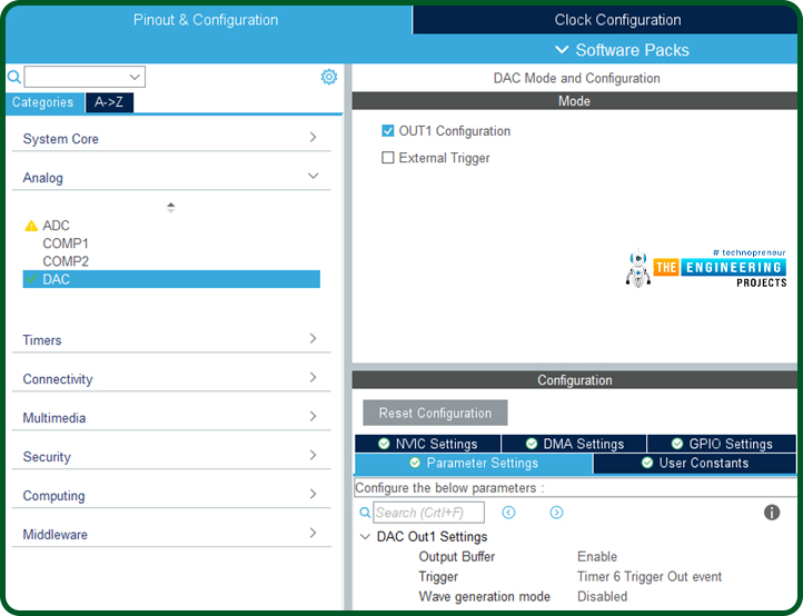
- Select DAC with following path: “Pinout & Configuration”-> Analog -> DAC. Select the Output 1 (OUT1 Configuration):
- In “Parameter Settings” the Output Buffer is enabled, Timer 6 is selected as Trigger Out Event and Wave generation mode is disabled.
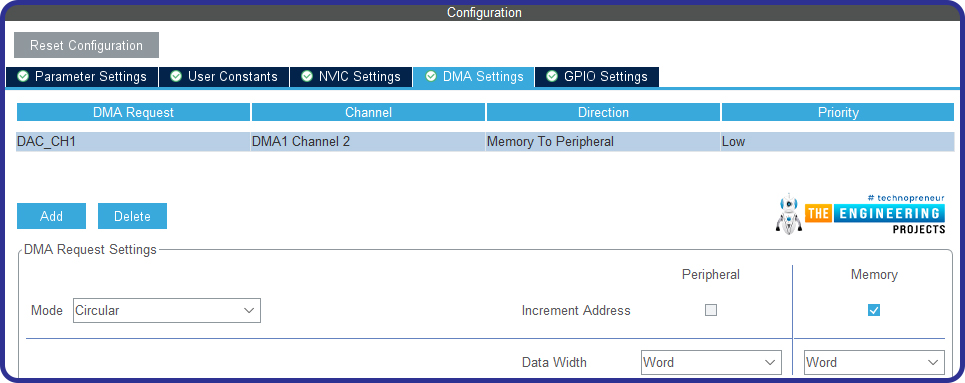
- Activate DMA to handle DAC using channel 2. The direction is Memory to Peripheral. The buffer mode is “circular”, and the data length is a word.
- Set interrupt related channel 2 of DMA
TIM 6 Configuration
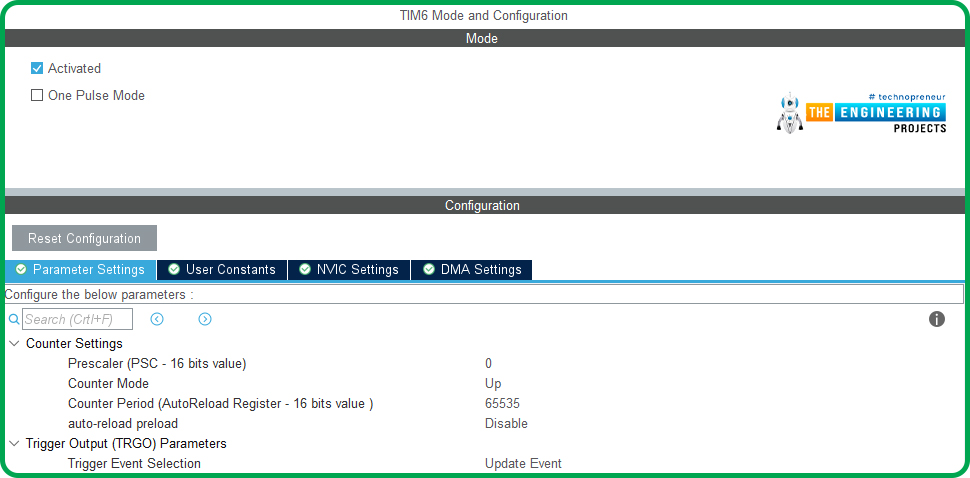
- We use TIM6 because is one of two timers used by uP to trigger the DAC output. At the moment we do not change the initial configuration, later we will see what we need.
- TIM6 -> NVIC Setting: flag “TIM6 interrupt and DAC1/DAC2 underrun error interrupts” to activate interrupts.

Sinewave generation
Let’s see mathematically how to reconstruct a sinewave starting from a given number of samples. The greater the number of samples, the more “faithful” the reconstructed signal will be. So, the sampling step is 2pi / ns where ns is the number of samples in this way, we have to save our samples in a vector of length ns. The values of every single element of the vector will be given by the following equation:
S[i] = (sin(i*(2π/ns))+1)
We know that the sinusoidal signal varies between 1 and -1 so it is necessary to shift it upwards to have a positive sinewave (therefore not with a null average value) therefore it must be moved to the middle of the reference voltage. To do this, it is necessary to retouch the previous equation with the following:
S[i] = (sin(i*(2π/ns))+1)*((0xFFF+1)/2)
Where 0xFFF is the maximum digital value of DAC (12bit) when the data format is 12 bits right aligned.
To set the frequency of the signal to be generated, it is necessary to handle the frequency of the timer trigger output (freq.TimerTRGO, in our case we use the TIM6) and the number of samples.
Fsinewave = freq.TimerTRGO/ns
In our case, we define Max_Sample = 1000 ( is uint32_t variable) and let’s redefine some values of the timer 6 initialization.
static void MX_TIM6_Init(void)
{
/* USER CODE BEGIN TIM6_Init 0 */
/* USER CODE END TIM6_Init 0 */
TIM_MasterConfigTypeDef sMasterConfig = {0};
/* USER CODE BEGIN TIM6_Init 1 */
/* USER CODE END TIM6_Init 1 */
htim6.Instance = TIM6;
htim6.Init.Prescaler = 1;
htim6.Init.CounterMode = TIM_COUNTERMODE_UP;
htim6.Init.Period = 100;
htim6.Init.AutoReloadPreload = TIM_AUTORELOAD_PRELOAD_DISABLE;
if (HAL_TIM_Base_Init(&htim6) != HAL_OK)
{
Error_Handler();
}
sMasterConfig.MasterOutputTrigger = TIM_TRGO_UPDATE;
sMasterConfig.MasterSlaveMode = TIM_MASTERSLAVEMODE_DISABLE;
if (HAL_TIMEx_MasterConfigSynchronization(&htim6, &sMasterConfig) != HAL_OK)
{
Error_Handler();
}
/* USER CODE BEGIN TIM6_Init 2 */
/* USER CODE END TIM6_Init 2 */
}
We have changed the following parameters:
htim6.Init.Prescaler = 1;
htim6.Init.Period = 100;
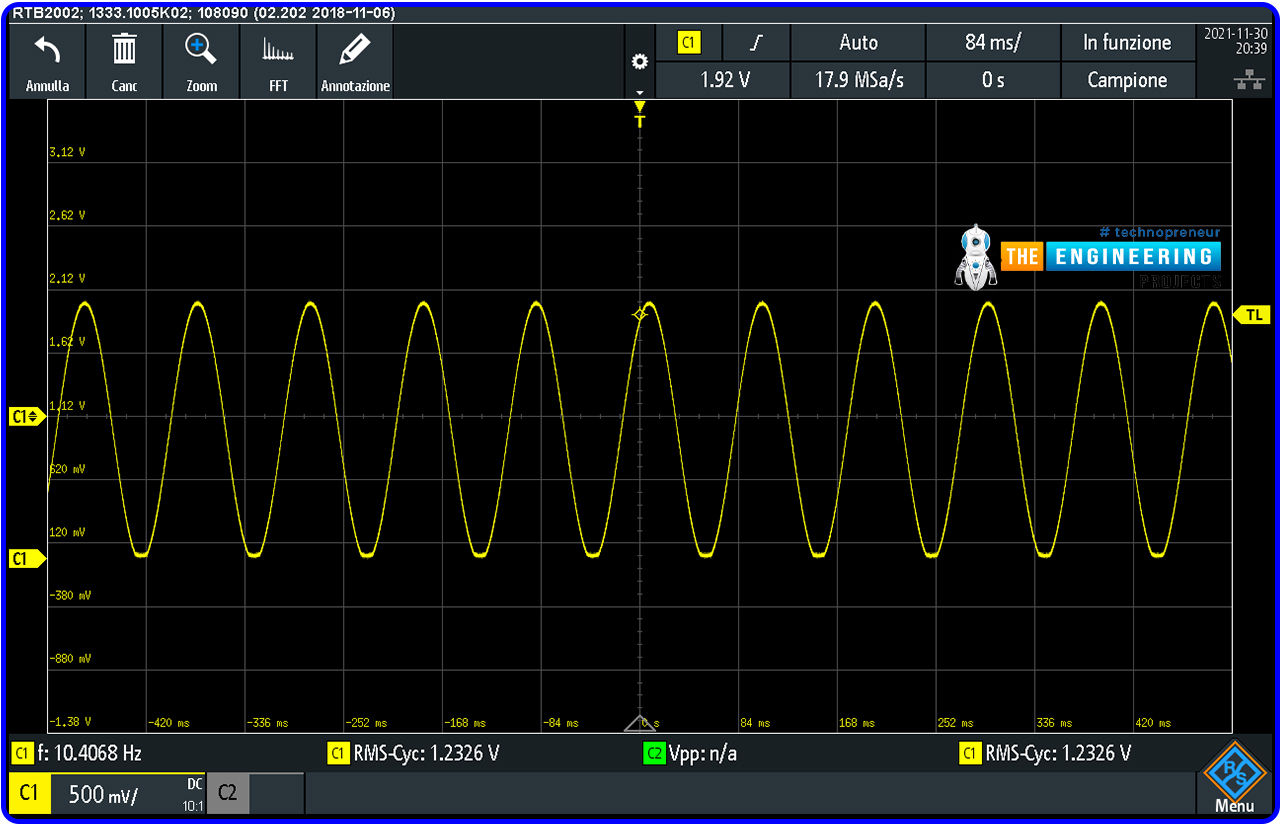
So with 1000 samples, the output sinewave will be a frequency of 10 Hz. We can change the number of samples (being careful not to use too few samples) or the “Init.Prescaler” and “Init.Period” values of timer 6.
Driving DAC in DMA mode with Timer
Using the DAC in DMA mode the HAL library makes available to handle the DAC another function to set the DAC output.
HAL_DAC_Start_DMA(DAC_HandleTypeDef* hdac, uint32_t Channel, uint32_t* pData, uint32_t Length, uint32_t Alignment)
Compared to the manual function we find two more parameters:
- uint32_t* pData is the peripheral buffer address;
- uint32_t Length is the length of data to be transferred from the memory to DAC peripheral.
As you can see from the following code we first need to include the “math.h” library, define the value of pigreco (pi 3.14155926), and write a function to save the sampled sinewave values in a array (we wrote a function declared as get_sineval () ).
#include “math.h”
#define pi 3.14155926
DAC_HandleTypeDef hdac;
DMA_HandleTypeDef hdma_dac_ch1;
TIM_HandleTypeDef htim6;
void SystemClock_Config(void);
static void MX_GPIO_Init(void);
static void MX_DMA_Init(void);
static void MX_DAC_Init(void);
static void MX_TIM6_Init(void);
uint32_t MAX_SAMPLES =1000;
uint32_t sine_val[1000];
void get_sineval()
{
for (int i =0; i< MAX_SAMPLES; i++)
{
sine_val[i] = ((sin(i*2*pi/MAX_SAMPLES)+1))*4096/2;
}
}
/* USER CODE END 0 */
- Once this is done, we can start the DAC by saving the sampled values of the sinewave in the buffer (* pdata) as shown below:
int main(void)
{
/* USER CODE BEGIN 1 */
/* USER CODE END 1 */
/* MCU Configuration——————————————————–*/
/* Reset of all peripherals, Initializes the Flash interface and the Systick. */
HAL_Init();
/* USER CODE BEGIN Init */
/* USER CODE END Init */
/* Configure the system clock */
SystemClock_Config();
/* USER CODE BEGIN SysInit */
/* USER CODE END SysInit */
/* Initialize all configured peripherals */
MX_GPIO_Init();
MX_DMA_Init();
MX_DAC_Init();
MX_TIM6_Init();
/* USER CODE BEGIN 2 */
get_sineval();
HAL_TIM_Base_Start(&htim6);
HAL_DAC_Start_DMA(&hdac, DAC_CHANNEL_1, sine_val, MAX_SAMPLES, DAC_ALIGN_12B_R);
/* USER CODE END 2 */
/* Infinite loop */
/* USER CODE BEGIN WHILE */
while (1)
{
/* USER CODE END WHILE */
/* USER CODE BEGIN 3 */
}
/* USER CODE END 3 */
}
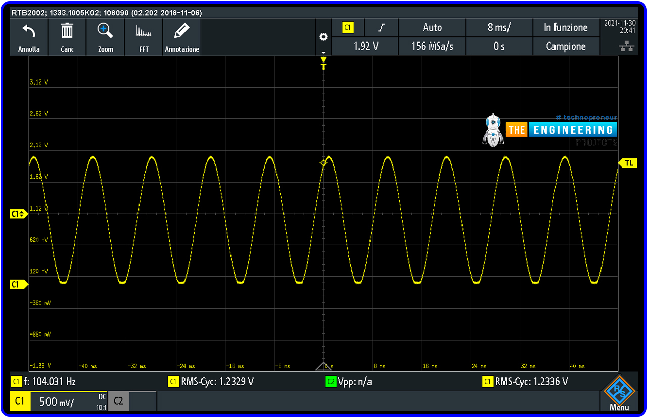
Now we just have to show the acquisition that the oscilloscope:
If we change the number of MAX_SAMPLE to 100 the sinewave will be a frequency of 100 Hz, but as can be seen from the acquisition, the number of samples, in this case, is a bit low.
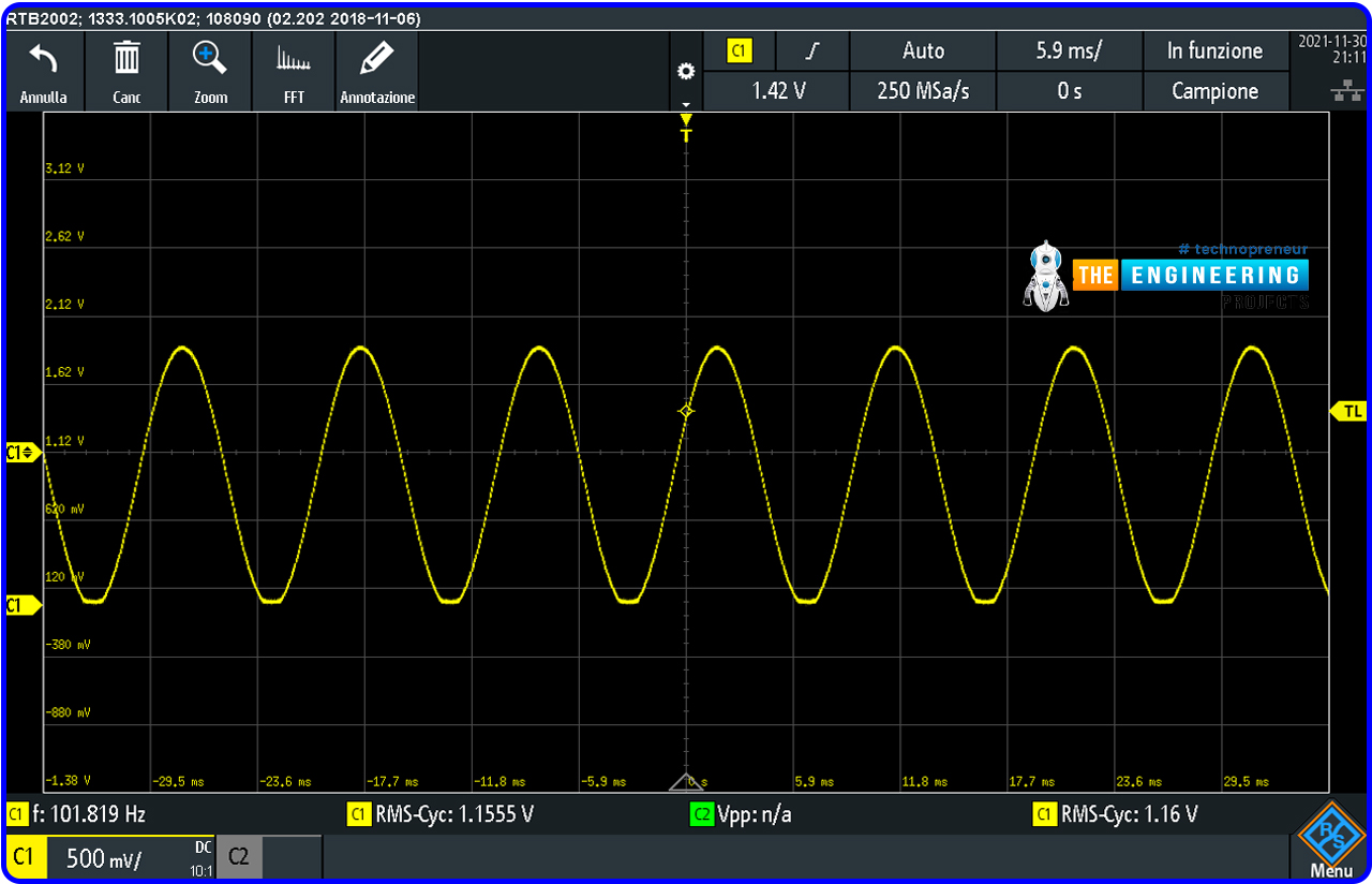
We can optimize the waveform by acting on timer 6 in order to increase the number of samples. For example by modifying htim6.Init.Period = 400
So, that was all for today. I hope you have enjoyed today’s lecture. Let me know if you have any questions. Thanks for reading. Take care !!! 
JLCPCB – Prototype 10 PCBs for $2 (For Any Color)
China’s Largest PCB Prototype Enterprise, 600,000+ Customers & 10,000+ Online Orders Daily
How to Get PCB Cash Coupon from JLCPCB: https://bit.ly/2GMCH9w
The post Using DAC with STM32 appeared first on The Engineering Projects.



No comments:
Post a Comment