Showing posts with label The Engineering Projects. Show all posts

Tuesday, 14 June 2022

Getting Past Legacy Software Pains in Requirements Management


Getting Past Legacy Software Pains in Requirements ManagementLegacy software refers to a business operating software that has been in use for a long time. This is older system software that is still relevant and fulfills the business needs. The software is critical to the business mission and the software operates on specific hardware for this reason.

Generally, the hardware in this situation has a shorter lifespan than the software. With time, the hardware becomes harder to maintain. Such a system will either be too complex or expensive to replace. For that reason, it continues operating.

What is a Legacy System?

Legacy software and legacy hardware are often installed and maintained simultaneously within an organization. The main changes to the legacy system typically only replace the hardware. That helps to avoid the onerous requirements management of the software certification process.

Which Businesses Have Legacy Systems?

Legacy systems operate in a wide range of business organizations, such as banks, manufacturing, energy companies, hospitals, and insurance companies. You can also find them in the defense industry, among other multifaceted business organizations.

Legacy Software Pains in Requirements Management

Only companies born in the digital age don’t face the problem of chronic legacy system pains, i.e. the distress of a lack of digital transformation. Legacy systems can involve unbearable complexity, mismatched skills, lack of innovation, bureaucracy, and so on.

Legacy systems form in organizations for many reasons. First, compliance issues and a rollout are often challenging to carry out all at once. There may be an ongoing project that needs the old system. There are also instances where decision-makers don’t like change.

However, the shortcomings of operating an old system are annoying and can also cause severe damage to the company. The pains of operating an old system include:

Getting Past Legacy Software Pains in Requirements Management

Legacy Systems Strategies are Not Prepared For Change

Legacy systems can include the ‘Stop and Start’ strategy. There are also long static periods or unchanging business, which was the mainstream way of running business operations throughout the industrial age. This means systems have a short period to make and adapt to any necessary changes, while business stops and waits for the wave of essential changes to finish.

The world doesn’t work like this anymore. Intermittent changes allow organizations with old systems to persist up to the next phase of evolution.

Fortunately, there is an alternate option called lean IT. The model advocates for making positive changes and continuous improvements and is aimed at avoiding getting stuck in waiting mode.

The lean IT model is well suited to data-oriented and digital systems, and helps discourage the myopic views that legacy systems foster in the first place.

Legacy Systems Create Security Problems

Legacy systems can pose several data security problems in an organization. Security is a prominent feature of the lean IT model. Continuous improvements and positive changes help to curb the latest threats. Old systems, because of their age, struggle with this.

Legacy systems may pose various challenges when fixing specific vulnerabilities, due to their large and inflexible nature. Making a fix in legacy systems can face delays because developers find it challenging to create one. Also, creating a repair is often not on the development team’s priority list. As a result, the fix ends up being very expensive.

Old systems can enter into a period where there is a danger to the organization due to their outdated security measures.

Inability to Meet Customers on Their Terms

The digital age has created tremendous opportunities, including those related to changing a company’s way of operations to benefit its users. Businesses that don’t have legacy systems find that when technology moves, the industry can move with it. They are ready to use any new generation that comes out and are prepared to download and install any new application that becomes popular.

Under these conditions, challenges can mount for a company stuck with an old system. Legacy systems have restrictions on using new applications. Businesses that have many customer interactions can encounter serious challenges.

Customers often go for features on the latest applications available in this digital era, such as Instagram and Windows 10 updates. Both of these have chatting options that legacy systems can’t enable. This is very much a missed opportunity.

Legacy Systems are Not Cost Effective

It may seem like legacy systems would be less expensive to maintain. However, that connotation changes over time, and circumstances often prove cost to be a pain point. Support and software updates for legacy systems are often much more expensive than current models, whose support and updates are always ready for seamless implementation.

The reason behind the additional maintenance cost is that knowledgeable software developers are hard to find. It involves a lot more work for software developers to offer the necessary continued care and updates for a legacy system than a current system.

Compatibility Issues Threaten Business Interaction

A legacy systems compatibility issue affects all users. We’re talking about the customers and business partners, suppliers, team members, and other associated users.

The legacy system will support file and data formats up to a certain point. But over time, these formats advance over and beyond what the legacy system can handle.

The evolution of support formats only takes a couple of years. In this event, the business will be stuck and experience pain points from using forms the customers or partners are no longer willing to use.

A company without legacy problems will adapt to successful implementation fast, aiming for better collaborations among users and team members. They also avoid waste in IT operations. Therefore, the future of the company’s business remains adaptable.

Getting Past Legacy Software Pains in Requirements Management

Lack of Storage Availability and Budget

Legacy systems are often full of lurking, untested problems. Support is often difficult to come by, leading to frustrating support interactions.

Customer support is critical, especially when you have large data sets or tight deadlines. Modern software development techniques make it easy to release and access track records. System data storage matters a lot to the users, so data storage and accessibility are key features in new systems that also come in handy when support is necessary.

Unhealthy for Employee Training

Look at the IT team members’ psychological aspects for a moment. What does operating a legacy system say to the workforce? It signals that it’s okay to work with an old system on one end while putting off addressing worries until later. The system solutions from the past are still working.

But an organization should not encourage this view in their employees, especially when training employees in new skills.

The method may still function, but it will be a massive liability for connectivity and security. Legacy systems also reduce productivity, lower team members’ morale, and repel some of the best talents. Employees with first-hand experience in new technology want to hold to that and have no interest in learning old systems.

“If it’s not broken, don’t fix it” is the IT professional’s general attitude. Though it does not stem from any bad intentions, it can cause a company severe problems down the road.

Proprietary Tools are Not Fun

Legacy systems tend to be clunky, extensive, and very proprietary. Changing or customizing them poses a serious challenge. But modern IT professionals prefer to use the latest techniques and have no interest in mastering old systems.

Some organizations’ software and hardware needs are different from other companies. Therefore, they need to build their custom software and hardware. New systems have smaller parts that make them flexible and easy to adopt. Specialized needs are no excuse for retaining legacy systems.

Getting Past Legacy Software Pains In Requirements Management

High-regulated industries have difficulty catching up with technology because of their complex systems. You may feel your company has outgrown its requirements management software, and you’re not alone.

The line between software and hardware becomes more and more blurred, and innovations are occurring faster than ever before. Requirements management providers may not supply the right software that matches the users’ goals, regardless of the notable reputation or how complex the software is. That can create severe problems that affect productivity.

Here are some common methods for how to work your way out from a legacy system into something much more helpful for yourself and your customers:

Getting Past Legacy Software Pains in Requirements Management

Working with Multiple Stakeholders in Mind

Highly regulated industries interact with many different stakeholders and players, which is good for their business. It is essential to value the input of the various roles and skill sets.

But problems can arise if one of these users doesn’t know how to use your requirements management software. Stakeholders bring their benefits to the company, but interfering with the system can be a recipe for compliance disaster.

To avoid such problems, look for software that flows with several roles and is seamless. Also, make sure your software integrates user-friendly traceability. Every user on the project needs to see the progress from beginning to end. This will prevent use problems from becoming a lasting problem and hindering productivity.

Timely Notifications to Help Meet Deadlines

Missing deadlines happen in many organizations. A team member needs to provide feedback but fails to do so on time. It could have been sent via email, Google, or Word document that someone didn’t know to monitor. Whichever means were used, the model of collaboration in place failed.

Review processes are quite complex these days, and you need collaboration software that sets clear intentions for the users. Real-time notification and editing will help keep team members on the truck.

Opt for a requirements management tool that prompts the next step to avoid falling into the trap. The requirements management software will help to prevent blame games – and it’s an excellent reason to suggest upgrading away from the legacy system altogether.

Accessibility and Intuitiveness

There may be instances where you want to carry out an essential process through the legacy system – but you are somehow locked out. You may have challenges finding the person who manages the system access rights and can get you back in the loop.

The situation can be frustrating and pose significant risks to the company, since one can attempt to break into the system for a couple of hours. This also wastes time. The desire to provide timely feedback with confidence is thwarted, which goes against the first intention of collecting the data.

The right requirements management tool should provide continuous data collection and growth. To achieve this, it should be open, accessible, and intuitive. The stakeholders will get motivation and provide constant input and collaboration, which is vital in keeping up with breakneck innovation.

An Upgrade Doesn’t Have to Spell Disaster

When an upgrade notification pops up on our screen, it’s normal to get skittish. There was once a very real fear of losing essential data and vital information with any kind of system update.

But this fear has dissipated with the advent of the cloud. A company no longer has to fear upgrading and fixing software requirements. It’s necessary to improve the security requirements and access some of the latest features.

It’s crucial to have a system that adapts quickly to update requirements. When purchasing legacy software, consider the opportunity costs of not upgrading and encountering the headache of being locked out of various unsupported platforms.

Data Storage, Security, and Availability

As part of evaluating your current system, investigate data storage safety during software development. Find out from existing customers how well your system releases the accurate document.

Whatever system you choose will be around for a long time, so you will need to measure your predicted needs from the vendor. You will be putting some of your crown jewels on the system you want to buy. They need to be safe.

Conclusion

We live in an age with the most innovative and disruptive products available to more people than ever. We have ultra-fast electric cars, self-piloted spaceships, and lifelike prosthetics. We also have some of the brightest minds toiling to help propel us into the future.

This means the regulatory environment now is more stringent, especially on public safety and the marketplace demands. There is a need to have a team ready to meet the ever-increasing demands of compliance.

To be on the safer side, you need to put in place a collaborative infrastructure to keep the team organized and detect mistakes of disconnected persons in real-time. The future of your company depends on it.

Frequently Asked Questions

In what ways can one modernize a legacy system?

Migrate. This allows the business to perform critical processes immediately. Legacy software may not be flexible enough to allow the expected modification. Also, your old system may not offer its users the right results. Legacy migration can be the better choice in this case.

The other option is extension. You may not need to replace a legacy system that still performs its core functions (especially if it still has some years of warranty remaining). Despite that, you can still modernize it by extending its capabilities.

How do you handle management pushing legacy systems?

Try to make concrete and practical recommendations on how to make the legacy system better. Provide evidence on how the improvements will lead to better performance. You may change minds by presenting realistic situations where the legacy system can still be helpful in the future with just a few additions.

The post Getting Past Legacy Software Pains in Requirements Management appeared first on The Engineering Projects.



Reasons Why 3D Printing Technology is Underrated


Reasons Why 3D Printing Technology is Underrated, 3d printing technology3D printing technology is one of the most progressive methods of creating objects in the market today. There are four different types of production techniques in manufacturing. These include subtractive manufacturing, casting, formation, and additive manufacturing.

Reasons Why Additive Manufacturing is a Superior Form of Manufacturing

Additive manufacturing is the technique of production that 3D printers use to create physical objects. Additive manufacturing is the manufacturing process in which you create an object from scratch by directly layering the raw material.

This technique is different from others because it does not create waste like subtractive manufacturing. It does not require manual effort and time like the formation process where you add force to a material to shape it, and it does not require tools and molds like casting to produce a functional product.

In conclusion, additive manufacturing requires no tools, has no waste, and needs zero cutting and complex procedures.

How Does Additive Manufacturing Work?

There are various types of additive manufacturing in the market. All of these processes are suitable for their respective fields and functions. A production house can use one of these techniques to create its design.

Direct Casting

Reasons Why 3D Printing Technology is Underrated, 3d printing technologyThe large scale 3D printer allows the production company to create a mold and cast-in-motion with the help of a dual head. The cast-in-motion technique cuts a lot of time and steps from the traditional molding and casting procedure. This procedure includes four steps. The first step is to feed the information into the printer and print the design.

After the design is complete, cure the product in an oven to enhance its mechanical properties. The cast of the product comprises a water-breakable mixture. Therefore, in the third step, soak the mold in water. It will degenerate, and you can finish your product in the last step for further use.

This process is rapid, and your production, which took weeks, now only takes a few days.

FDM

Fusion deposition modeling is a typical process of manufacturing in an additive process. A domestic printer uses this process to create designs. This printer is easy to use as you need to fill the printer with filament from one end, and it will produce your design on the other end.

This process needs a design, the software cuts the design into thin digital slices, and once the data is in the printer, it will create the product automatically. It may be easy to use, but large-scale industries do not prefer it for its poor finish and fragile material.

SLA Printing

The process of Stereolithography is unique as it uses photosensitive resin to solidify the design out of liquid polymer. It is a precise way of creating objects from resin, and it does not require as much time as other printing methods. The UV rays cure the liquid polymer on top of the layers. It creates an illusion of an object being born from the liquid.

Laser Sintering

The laser sintering method is dangerous in public places, but it is practical for enormous industries. It uses refined metal powder as raw material. The machine uses a laser to create a solid object from this metal dust. The printer does have a container box for metal powder but inhaling this powder can be dangerous.

NASA and other mechanical corporations use this technique to build parts for air crafts, planes, cars, and other automobiles. If the production house follows all the SOPs, this method is one of the fastest methods of creating parts.

Poly Jet Method

The poly jet method is a mixture of FDM and SLA printing. The machine uses thin layers of resin and layers are like a filament, and the UV light instantly cures the resin in place. This technique is valuable for rapid prototyping, fixtures, and creating functional moving parts.

The Revolutionary Implications of 3D Printing

Multiple applications and implications of 3D printing suggest that it has revolutionized the world. 3D printing has minimized the connection between production and consumption. A consumer can directly produce a design in a short time. The time for a product to reach the consumer has drastically reduced.

The emergency disaster zone fixtures are possible with the help of instant 3D printing. It also inspires the younger generation to create and practically use their theoretical knowledge. It has inspired the world to connect virtual reality to physical reality. And all of this is just the beginning of what 3D technology has to offer.

The post Reasons Why 3D Printing Technology is Underrated appeared first on The Engineering Projects.


Tuesday, 31 May 2022

JMP & LBL Instructions in Ladder Logic Programming


branching logic in Ladder logic, jump in ladder logic, label in ladder logic, jmp ladder logic, lbl ladder logicHi friends, I hope you are very well; today in this tutorial, we will practice conditional jumping for performing some code at the occurrence of some conditions. Like any other programming language, jumping is one of the most common approaches to transfer the execution from its sequential mode to run different processes or instructions marked by a label and bypassing the lines of codes in between the last executed transaction before the jump instruction and the labeled instruction whom the program is going to move to. The good thing about this technique is shortening the scan cycle of the program due to not running the whole program. However, using jumping techniques in coding is very dangerous. It would help if you were careful of missing some open cases before going anywhere in the code. For example, let us say that we started one process. In the middle of the process’s sequence, one jump instruction is used to run some logic under some conditions, so jumping means leaving or skyping for some reason and going running some logic or code. Therefore, we should consider the skipped instructions’ effects and consequences on the whole process and program logic. In addition, because any jump instruction can target any label and many jump instructions can target the same label, you should pay great attention to make sure you name the correct label according to the designed logic to avoid losing the reason you plan your program to do. I know you might take it easy now and can not imagine someone right wrong label by mistake. But, when you will be writing a large-scale project which contains hundreds or even thousands of rungs and has couples of dozens of labels, in that case, you can quickly mistakenly write the wrong label.

JMP and LBL instructions

To perform jumping in the ladder logic program, two instructions are together, as shown in Fig. 1. The first instruction is JMP which tells the PLC you need to jump from where the jump instruction is to where you find the LBL instruction.

branching logic in Ladder logic, jump in ladder logic, label in ladder logic, jmp ladder logic, lbl ladder logic

Fig. 1: JMP and LBL instructions

Now how to know the label to whom you want the program execution to go or jump? Well, that is an excellent question, and the answer is that you should specify the label name as a parameter of jump instruction and the label instruction. Therefore, you can notice, my friends, if Fig. 2, the JMP and LBL instructions have a question mark denoting you should specify the label name, which is the next station to programme execution.

branching logic in Ladder logic, jump in ladder logic, label in ladder logic, jmp ladder logic, lbl ladder logic

Fig. 2: Jump and Label instruction showing the label name above of them

Jump instruction ladder logic example

Now friends, let us see how jump and label instructions work together, as shown in fig. Three depicts a straightforward example of ladder logic in which JMP and LBL instruction work together, referring to the same label Q2:0. In this example, if input contact I1/0 is activated, JMP instruction will take the execution where the Q2:0 label “LBL” instruction is. As a result, the rung 001 has been bypassed.

branching logic in Ladder logic, jump in ladder logic, label in ladder logic, jmp ladder logic, lbl ladder logic

Fig. 3: ladder logic example for jump and label instructions

How about going with a situation where we need to employ JMP and LBL instruction? Yes, in the example shown in fig. 4, You can notice here in this example. There are a couple of motors and for these motors. We need to. Use Siri. The command of the jump. And in combination with the uh label instruction. 2. Let some motors work in one scenario. And in another scenario, we will let some of these motors worworkd the others are not working. So you can imagine if you are working with Couples of pumps and want to run all pumps together in one scenario, so you do not activate the JMP command. But, in another scenario, if you’re running some of these pumps. So what we are going to do here in this example is to activate the JMP command to bypass some of these pumps, which are between the JMP and LBL commands.

branching logic in Ladder logic, jump in ladder logic, label in ladder logic, jmp ladder logic, lbl ladder logic

Fig. 4: a real example of jump instruction

Figure 5 depicts the execution of the sample program that demonstrates JMP instruction. This case shows what happened in the first scenario example. If we do not activate jump instruction in rung 3, then all motors 1,2,3,4,5,6 and 7 will run based on the status of their firing contacts which are I:0 0 to 7, respectively. And the program execution continues running other motors after the JMP as it is not activated by touch I:0 3.

branching logic in Ladder logic, jump in ladder logic, label in ladder logic, jmp ladder logic, lbl ladder logic

Fig. 5: test when JMP is not activated

On the other hand, Fig. 6 depicts the second scenario when activating JMP instruction by contact I0:3 at run number 3. By activating the jump command, We can notice only the motor before jump instructions are running based on their command contacts when the pumps in between jumps and label commands are bypassed, and the other engines after label instruction are running. So motors 1,2 and 3 are running, motors 4,5 and 6 have been ignored by activation of jump command instruction, while motor seven is running, which is at label command.

branching logic in Ladder logic, jump in ladder logic, label in ladder logic, jmp ladder logic, lbl ladder logic

Fig. 6: test when JMP is activated

What’s next,

I want to thank you all for following me in this short and essential tutorial that can help you utilize the jump and label command instructions to control the logic flow of your program based on the situations and the logic design of your program. So now you can perform safety control to avoid running some equipment under some circumstances to protect the operator and equipment. In addition, you can run many logic scenarios in one program based on the status of input and output devices. In the following tutorial, we will take something neer to jump, which is subroutines, showing you how you can make your program modular and divided into subroutines to be organized and readable and easy to maintain, follow, and being modified. So be ready, and let us meet soon to learn and practice the new ladder logic programming tutorial.

The post JMP & LBL Instructions in Ladder Logic Programming appeared first on The Engineering Projects.


Analog Input Scaling in Ladder Logic Programming


Scaling analog inputs, Scaling with parameters, analog input scaling, analog input scaling in plc simulator, ladder logic analog input scaling, analog input scaling in ladder logicHi friends and hope you are doing very well. Today we would like to take one tutorial which is very essential in the industry which is analog input processing for handling analog measurements of physical signals like temperature, humidity, pressure, distance, flow and level of liquids, etc. Typically, sensors produce two types of analog signals to represent the equivalent measured signal which is current and voltage signals. The currently produced signals would be within the range of 4-20 mAwhile voltage signals are in the range of 0-10 v. because, that output signals represent physical signals, the limits of output signals are 0 to 10 v for voltage based sensors and 4 to 20 mA for current-based sensors, these values should be scaled to represent the equivalent value as regards to physical signals. By completing this tutorial, we will have elaborated on the concept of handling analog signals and how we scale them to represent the physical signals. In addition, we will go through practical examples for handling analog inputs with ladder programming and then we will enjoy practicing these examples on the simulator to validate the written ladder code and show practically the analog processing in PLC.

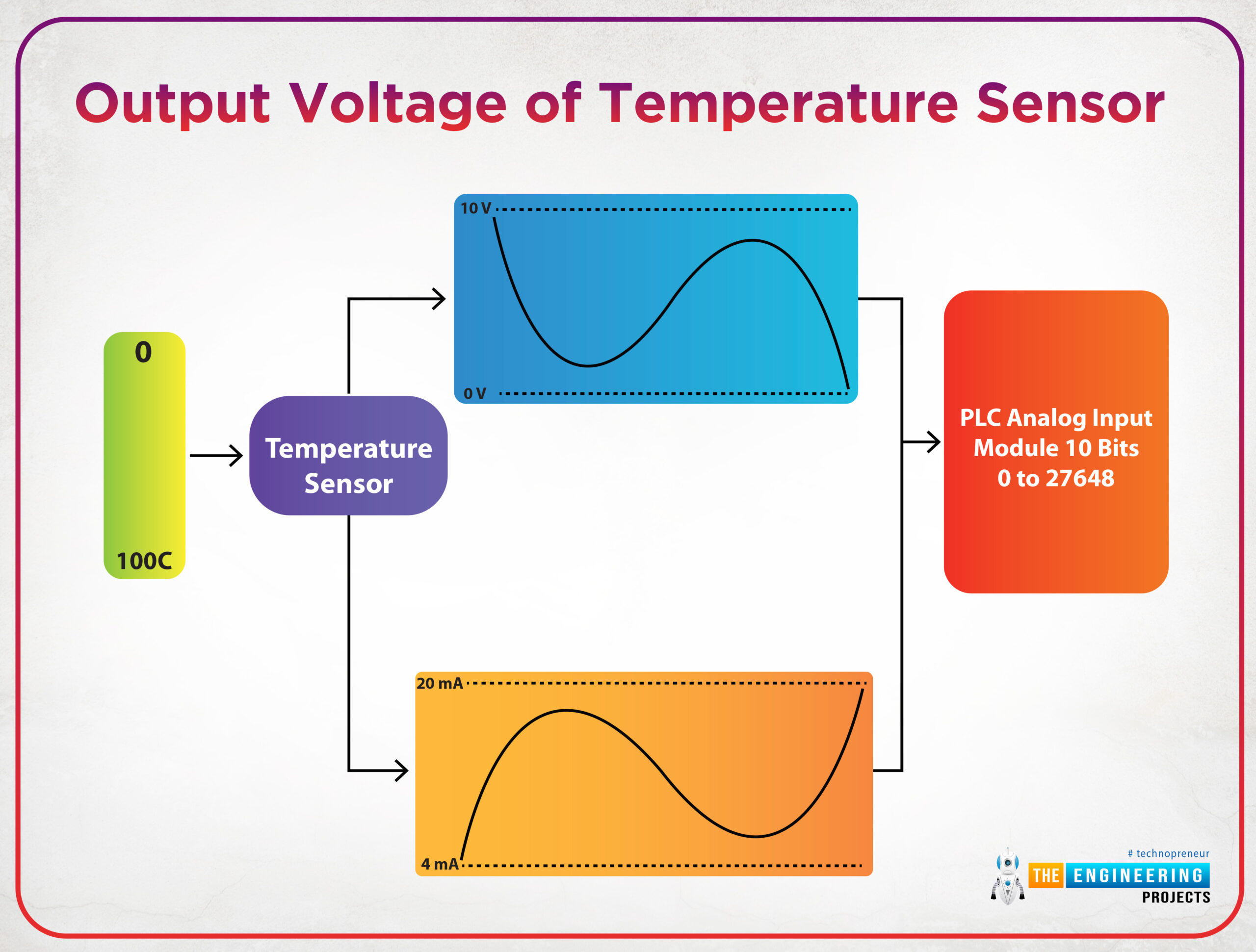
In computer systems, plc, and microcontrollers all processing work that has been done inside is processed in digital which is 0 and 1 representation. So, one may ask how analog signals which change continuously within a specific range could be processed by computers, PLCs, or microcontrollers? Well, that is an exciting question and its answer will open the door to show the aim of this tutorial. Figure 1 shows an example of analog signals of the voltage that represents the temperature sensor reading.

Scaling analog inputs, Scaling with parameters, analog input scaling, analog input scaling in plc simulator, ladder logic analog input scaling, analog input scaling in ladder logic

Fig. 1: Output voltage of temperature sensor

As you see in fig. 1, the output of the temperature sensor would be either a voltage signal or a current signal based on the type of the sensor. And the output of sensors is applied to the analog input module that converts the analog signal to a digital signal to be processed digitally by the PLC.

Scaling analog inputs

The output signals of sensors either voltage or current signal should be scaled to represent the physical signal and at the same time, it has its equivalent digital values. For example, let the temperature that is being measured has a range between 0 to 100 °C, and the sensor that we use produces voltage output from 0 to 10 v. Therefore, each 0.1 v change in voltage is equivalent to a change of 1°C. Also, assuming the maximum digital value that can be received is 4000. So, 0 V is equivalent to 0 as a digital value and 10 voltage is equivalent to 4000 as a digital value. So, it is crucial to scale the output voltage to determine accurately the equivalent change in sensors’ reading in terms of voltage to represent the temperature in digital value and the real range of the physical signal.

Scaling with parameters

Again, we have two sides to be scaled from one to the other. Therefore, the parameters that are needed for achieving such scaling are as follows:

  • The input value: represents the physical signal that comes out from a sensor. And it typically could be from 0-10v for voltage-based sensors, or it could be 4-20mA for current sensors type.
  • The scaled value represents the digital equivalent of that value. And it depends on the word size or the number of bits that we use for representation in digital format. For example, for 16 bits size, the scaled value is up to which is +/- 32768.

So we can imagine together now the scaling function block in ladder logic should be as shown in fig. 2. It shows the input minimum and maximum which could be 0 and 10v or 4 and 20mA. In addition, there are scaled min and max which could be from 0 to 32768 for 16 bits size conversion.

Scaling analog inputs, Scaling with parameters, analog input scaling, analog input scaling in plc simulator, ladder logic analog input scaling, analog input scaling in ladder logic

Fig.2: the SCP block in Allen Bradley

Analog input processing in Ladder logic

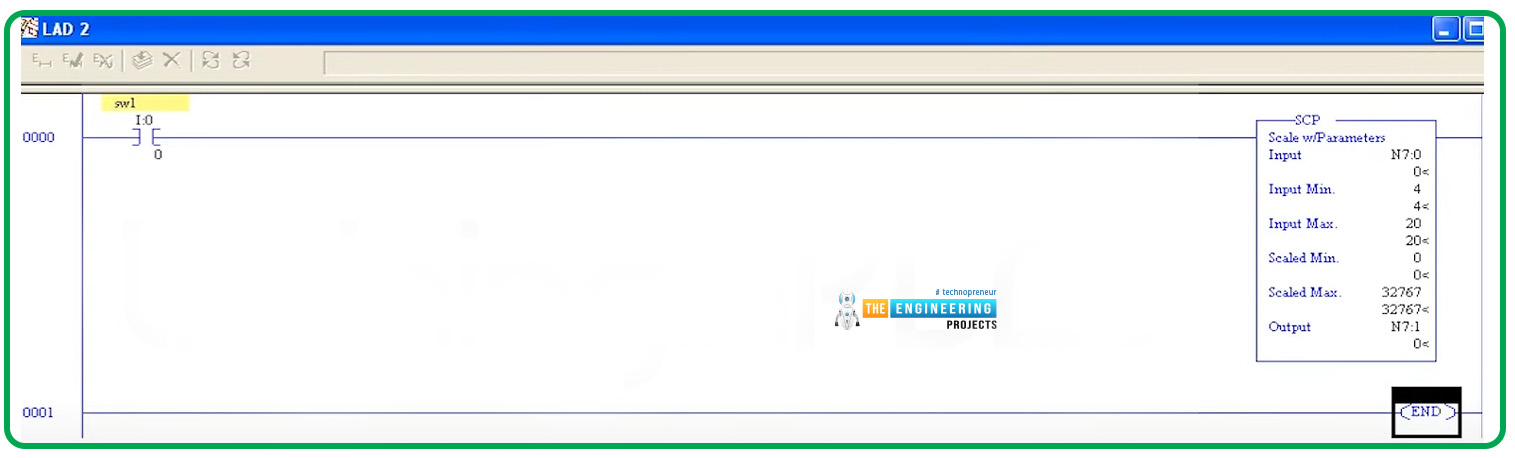
We are going to show a complete example of analog input processing in Siemens and AB as well to present the merits of analog conversion in both brands. Figure 3 shows a primitive rung of the ladder logic program that processes the analog input reading. The ladder rung uses a scaling with parameters (SCP) block that includes an input minimum of 4mA and an input maximum of 20mA. And it uses a scaled range from 0 to 32767 because it utilizes 16-bits word for representing the digital data.

Scaling analog inputs, Scaling with parameters, analog input scaling, analog input scaling in plc simulator, ladder logic analog input scaling, analog input scaling in ladder logic

Fig. 3: Ladder logic rung for analog input processing

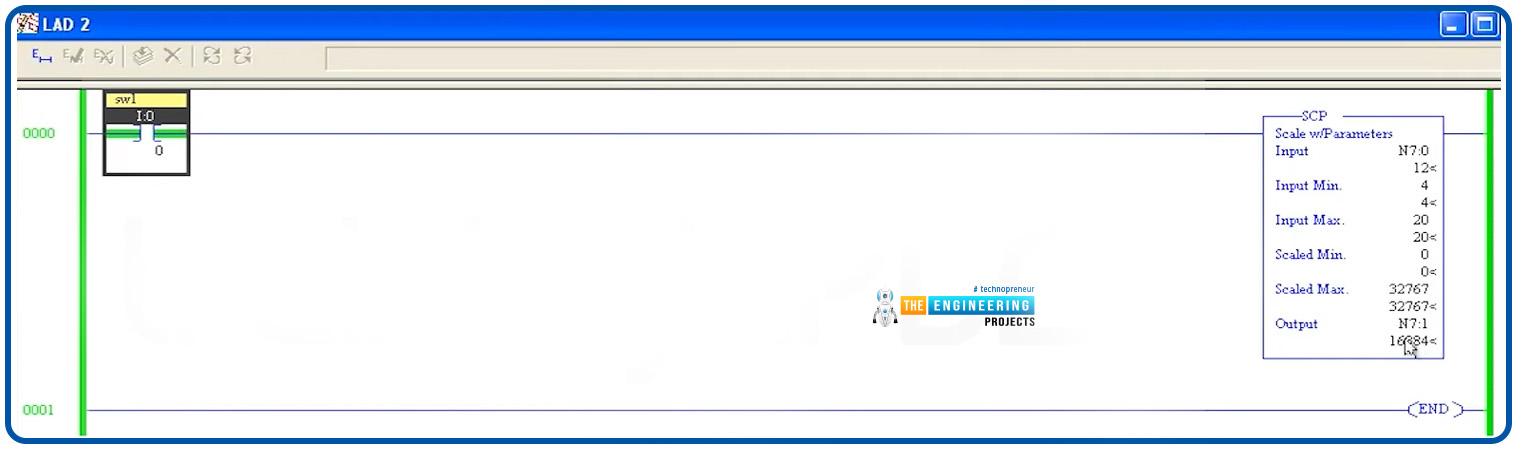
Figure 4 shows the run of the simple example which shows up the processing of analog inputs. It shows that, when the input measured value was 12mA, the output was 16884 which is pretty accurate. It is good to mention that, the output is limited to be within the range of the scaled min and max meaning that it should be from 0 to 32767.

Scaling analog inputs, Scaling with parameters, analog input scaling, analog input scaling in plc simulator, ladder logic analog input scaling, analog input scaling in ladder logic

Fig. 4: Testing analog processing by the simulator

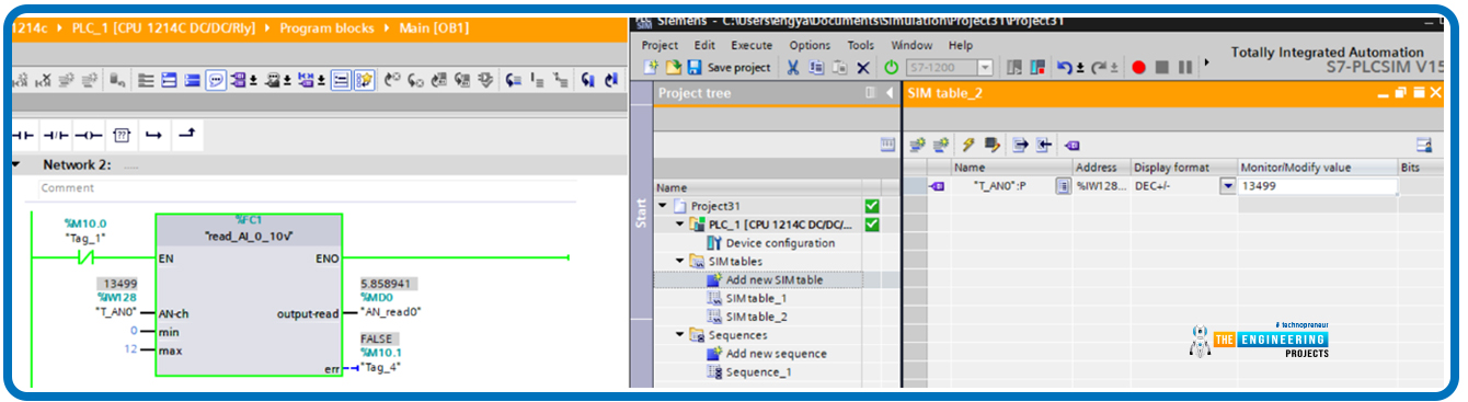
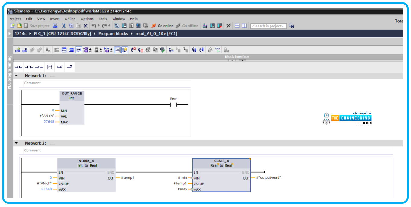
Let us give another example but in siemens s7-1200 which is represented by Fig. 5. The ladder code is very simple and it consists of two runs as shown in fig. 5; the first one is for validating the reading to be within the range which is from 0 to 27648 and the second rung is the main one which performs the analog processing in two steps. Firstly it normalizes the input based on the aforementioned range and then it scales the output back to represent it in the output signal format. In this example, we measure a battery voltage that is typically located in the range of 0 to 12v. Therefore, the min and max parameters in the scale_X block should be 0 and 12 v respectively.

Scaling analog inputs, Scaling with parameters, analog input scaling, analog input scaling in plc simulator, ladder logic analog input scaling, analog input scaling in ladder logic

Fig. 5: Example of processing analog inputs in Siemens S7-1200

Figure 6 demonstrates the test of the analog processing showing the output reported 5.858941 when the reading was 13499 which is high accuracy.

Scaling analog inputs, Scaling with parameters, analog input scaling, analog input scaling in plc simulator, ladder logic analog input scaling, analog input scaling in ladder logic

Fig. 6: Simulation of processing analog inputs in Siemens S7-1200

What’s next

I am truly thrilled to have you shared with me such a very important tutorial about analog input processing and scaling with parameters because this is a very common operation you might see in every operation in the industry as there are hundreds of sensors that read analog physical signals and be processed by the controller for deciding the next stage of the operation. Next time we are going to talk about jumping and branching techniques in the ladder logic program. So please be ready to meet very soon and learn together and enjoy practicing plc ladder programming

The post Analog Input Scaling in Ladder Logic Programming appeared first on The Engineering Projects.


Sunday, 29 May 2022

Interfacing PIR Motion Sensor and Raspberry Pi Pico Module with MicroPython


Hello readers, I hope you all are doing great. In this tutorial, we will learn how to interface the PIR sensor to detect motion with the Raspberry Pi Pico module and MicroPython programming language. Later in this tutorial, we will also discuss the interrupts and how to generate an external interrupt with a PIR sensor.

Before interfacing and programming, the PIR and Pico boards let’s first have a look at the quick introduction to the PIR sensor and its working.

Interfacing PIR Motion Sensor and Raspberry Pi Pico Module with MicroPython, PIR with PICO, PIR Pico, PIR Sensor PICO, Pico PIR sensor, Motion detection with Raspberry Pi Pico

Fig. 1 Raspberry Pi Pico and PIR sensor

PIR motion sensor and its working

PIR stands for Passive Infrared sensors and the PIR module we are using is HC-SR501. As the name suggests the PIR or passive infrared sensor, produces TTL (transistor transistor logic) output (that is either HIGHT or LOW) in response to the input infrared radiation. The HC-SR501 (PIR) module is featured a pair of pyroelectric sensors to detect heat energy in the surrounding environment. Both the sensors sit beside each other, and when a motion is detected or the signal differential between the two sensors changes the PIR motion sensor will return a LOW result (logic zero volts). It means that you must wait for the pin to go low in the code. When the pin goes low, the desired function can be called.

In the PIR module, a fresnel lens is used to focus all the incoming infrared radiation to the PIR sensor.

Interfacing PIR Motion Sensor and Raspberry Pi Pico Module with MicroPython, PIR with PICO, PIR Pico, PIR Sensor PICO, Pico PIR sensor, Motion detection with Raspberry Pi Pico

Fig. 2 PIR motion sensor

The PIR motion sensor has a few setting options available to control or change its behaviour.

Two potentiometers are available in the HC-SR501 module as shown in the image attached below (Fig. 3). Sensitivity will be one of the options. So, one of the potentiometers is used to control the sensing range or sensitivity of the module. The sensitivity can be adjusted based on the installation location and project requirements. The second potentiometer (or the tuning option) is to control the delay time. Basically, this specifies how long the detection output should be active. It can be set to turn on for as little as a few seconds or as long as a few minutes.

Interfacing PIR Motion Sensor and Raspberry Pi Pico Module with MicroPython, PIR with PICO, PIR Pico, PIR Sensor PICO, Pico PIR sensor, Motion detection with Raspberry Pi Pico

Fig. 3 HC-SR501 PIR sensor module

Thermal sensing applications, such as security and motion detection, make use of PIR sensors. They’re frequently used in security alarms, motion detection alarms, and automatic lighting applications.

Some of the basic technical specifications of HC-SR501 (PIR) sensor module are:

Interfacing PIR Motion Sensor and Raspberry Pi Pico Module with MicroPython, PIR with PICO, PIR Pico, PIR Sensor PICO, Pico PIR sensor, Motion detection with Raspberry Pi Pico

Table: 1 HC-SR501 technical specification

Hardware and software components required

  1. Raspberry Pi Pico development board
  2. PIR motion sensor (HC-SR5010
  3. Jumper wires
  4. Breadboard
  5. Thonny IDE (installed)
  6. USB cable

Interfacing PIR Motion Sensor and Raspberry Pi Pico Module with MicroPython, PIR with PICO, PIR Pico, PIR Sensor PICO, Pico PIR sensor, Motion detection with Raspberry Pi Pico

Fig. 4 Hardware components required

Interfacing the PIR sensor module with Raspberry Pi Pico

The HC-SR501 module has three interfacing pins VCC, GND and OUT. The VCC pin is to power up the board and should be connected to the 3.3V pin of the Raspberry Pi Pico board. The ‘OUT’ pin provides the TTL (Transistor-Transistor Logic) output. The TTL output is either High or LOW depending upon the electromagnetic input received.

Raspberry Pi Pico module has 26 multifunctional GPIO pins. The ‘OUT’ pin of the PIR sensor can be connected to any of the GPIO pins of the Raspberry Pi Pico.

Interfacing PIR Motion Sensor and Raspberry Pi Pico Module with MicroPython, PIR with PICO, PIR Pico, PIR Sensor PICO, Pico PIR sensor, Motion detection with Raspberry Pi Pico

Table: 2 Interfacing HC-SR501 and Pico

Interfacing PIR Motion Sensor and Raspberry Pi Pico Module with MicroPython, PIR with PICO, PIR Pico, PIR Sensor PICO, Pico PIR sensor, Motion detection with Raspberry Pi Pico

Fig. 5 Interfacing PIR with Pico module

Programming with Thonny IDE and MicroPython

Before writing the MicroPython program make sure that you have the installed integrated development environment (IDE) to program the Pico board for interfacing the PIR sensor module.

There are multiple development environments available to program the Raspberry Pi Pico (RP2040) with MicroPython programming language like VS Code, uPyCraft IDE, Thonny IDE etc.

In this tutorial, we are using Thonny IDE with the MicroPython programming language (as mentioned earlier). We already published a tutorial on how to install the Thonny IDE for Raspberry Pi Pico Programming.

Now, let’s write the MicroPython program to interface the PIR (HC-SR501) and Pico modules and implement motion detection with Raspberry Pi Pico:

Importing Necessary Libraries

The first task is importing the necessary libraries and classes. To connect the data (OUT) pin of the PIR sensor module with Raspberry Pi Pico we can use any of the GPIO pins of the Pico module. So, here we are importing the ‘Pin’ class from the ‘machine’ library to access the GPIO pins of the Raspberry Pi Pico board.

Secondly, we are importing the ‘time’ library to access the internal clock of RP2040. This time module is used to add delay in program execution or between some events whenever required.

Interfacing PIR Motion Sensor and Raspberry Pi Pico Module with MicroPython, PIR with PICO, PIR Pico, PIR Sensor PICO, Pico PIR sensor, Motion detection with Raspberry Pi Pico

Fig. 6 Importing necessary libraries

Object Declaration

Next, we are declaring some objects. The ’led’ object represents the GPIO pin to which the LED is connected (representing the status of PIR output) and the pin is configured as an output.

The ‘PirSensor’ object represents the GPIO pin to which the ‘OUT’ pin of HC-SR501 is to be connected which is GPIO_0. The pin is configured as input and pulled down.

Interfacing PIR Motion Sensor and Raspberry Pi Pico Module with MicroPython, PIR with PICO, PIR Pico, PIR Sensor PICO, Pico PIR sensor, Motion detection with Raspberry Pi Pico

Fig. 7 Object declaration

Creating a function to detect motion

A ‘motion_det()’ function is defined to check the status of the PIR sensor and degenerate an event in response.

The status of the PIR sensor is observed using the ‘PirSensor.value()’ command. The default status of GPIO_0 is LOW or ‘0’ because it is pulled down. We are using a LED to represent the status of the PIR sensor. Whenever a motion is detected the LED will change its state and will remain in that state for a particular time interval.

If the motion is detected, the status of the GPIO_0 pin will turn to HIGH or ‘1’ and the respective status will be printed on the ‘Shell’ and simultaneously the status of led connected to GPIO_25 will also change to HIGH for 3sec. Otherwise, the “no motion” status will be printed on the Shell.

Interfacing PIR Motion Sensor and Raspberry Pi Pico Module with MicroPython, PIR with PICO, PIR Pico, PIR Sensor PICO, Pico PIR sensor, Motion detection with Raspberry Pi Pico

Fig. 8 creating a function

Running the motion detection function

Here we are using the ‘while’ loop to continuously run the motion detection function. So, the PIR sensor will be responding to the infrared input continuously with the added delay.

Interfacing PIR Motion Sensor and Raspberry Pi Pico Module with MicroPython, PIR with PICO, PIR Pico, PIR Sensor PICO, Pico PIR sensor, Motion detection with Raspberry Pi Pico

Fig. 9 mail loop

Code

# importing necessary libraries

from machine import Pin

import time

# Object declaration

led = Pin(25, Pin.OUT, Pin.PULL_DOWN)

PirSensor = Pin(0, Pin.IN, Pin.PULL_DOWN)

def motion_det():

if PirSensor.value() ==1: # status of PIR output

print(“motion detected”) # print the response

led.value(1)

time.sleep(3)

else:

print(“no motion”)

led.value(0)

time.sleep(1)

while True:

motion_det()


Results

    • Connect your Raspberry Pi Pico board with your system and select the MicroPython interpreter.
    • Create a new program in Thonny IDE and paste the above code.
    • Save the program to either on your system or on Raspberry Pi Pico.
    • To see the output result (printed) enable the ‘Shell’.
    • To enable the Shell got to View >> Shell.

Interfacing PIR Motion Sensor and Raspberry Pi Pico Module with MicroPython, PIR with PICO, PIR Pico, PIR Sensor PICO, Pico PIR sensor, Motion detection with Raspberry Pi Pico

Fig. 10 Fig enable Shell

  • Run the program by clicking on the ‘Run’

Interfacing PIR Motion Sensor and Raspberry Pi Pico Module with MicroPython, PIR with PICO, PIR Pico, PIR Sensor PICO, Pico PIR sensor, Motion detection with Raspberry Pi Pico

Fig. 11 Output on Shell

Interfacing PIR Motion Sensor and Raspberry Pi Pico Module with MicroPython, PIR with PICO, PIR Pico, PIR Sensor PICO, Pico PIR sensor, Motion detection with Raspberry Pi Pico

Fig. 12 Motion detected with LED ‘ON’

Generating External interrupt with Raspberry Pi Pico and PIR sensor modules

Now let’s take another example where we will discuss the interrupts with Raspberry Pi Pico.

Interrupts comes into existence in two conditions. First one is when a microcontroller is executing a task or a sequence of dedicated tasks and along with that continuously monitoring for an event to occur and then execute the task arriving with that particular event. So, instead of continuously monitoring for an event, a microcontroller can directly jump to a new task whenever an interrupt occurs meanwhile keeping the regular task on halt. Thus we can avoid the wastage memory and energy.

Interfacing PIR Motion Sensor and Raspberry Pi Pico Module with MicroPython, PIR with PICO, PIR Pico, PIR Sensor PICO, Pico PIR sensor, Motion detection with Raspberry Pi Pico

Fig. 13 Interrupt

In second case, a microcontroller will start executing the task only when an interrupt occurs. Otherwise the microcontroller will remain in standby or low power mode (as per the instruction provided).

In this example, we are going to implement the second case of interrupt. Where, we are using the PIR sensor to generate an interrupt. The Raspberry Pi Pico will execute the assigned task only after receiving an interrupt request.

Interrupts can either be external or an internal one. Internal interrupts are mostly software generated for example timer interrupts. On the other hand, external interrupts are mostly hardware generated for example using a push button, motion sensor, temperature sensor, light detector etc.

In this example, we are using the PIR sensor to generate an external interrupt. Whenever the motion is detected, a particular group of LEDs will turn ON (HIGH) while keeping rest of the LEDs in OFF (LOW) state. A servo motor is also interfaced with the Raspberry Pi Pico board. The motor will start rotating once an interrupt is being detected.

We already published tutorial on interfacing a servo motor with Raspberry Pi Pico. You can follow our site for more details.

Interfacing PIR Motion Sensor and Raspberry Pi Pico Module with MicroPython, PIR with PICO, PIR Pico, PIR Sensor PICO, Pico PIR sensor, Motion detection with Raspberry Pi Pico

Fig. 14 Schematic_2

Now let’s write the MicroPython program to generate an external interrupt for raspberry Pi Pico with PIR sensor.

Importing libraries

As we discussed earlier, in our previous example the first task is importing necessary libraries and classes. Rest of the modules , are similar to the previous example except the ‘PWM’ one.

The ‘PWM’ class from ‘machine’ library is used to implement the PWM on the servo motor interfaces with the raspberry Pi Pico board.

Interfacing PIR Motion Sensor and Raspberry Pi Pico Module with MicroPython, PIR with PICO, PIR Pico, PIR Sensor PICO, Pico PIR sensor, Motion detection with Raspberry Pi Pico

Fig. 15 importing libraries

Object Declaration

In this example, we are using three different components a PIR sensor, a servo motor, and some LEDs. Object are declared for each component. The object ‘ex_interrupt’ represents the GPIO pin to which the PIR sensor is connected where the pin is configured as an input one and pulled down.

The second object represents the GPIO pin to which the servo motor is connected. The ‘led_x’ object represents the GPIO pins to which the peripheral LEDs are connected. Here we are using six peripheral LEDs.

Interfacing PIR Motion Sensor and Raspberry Pi Pico Module with MicroPython, PIR with PICO, PIR Pico, PIR Sensor PICO, Pico PIR sensor, Motion detection with Raspberry Pi Pico

Fig. 16 Object declaration

  • We are declaring a global variable ‘pir_output’ to represent the status of PIR output or motion being detected or not. When no motion is detected the state of the variable will remain in default state that is ‘False’. Whenever the motion is detected the state of ‘pir_output’ variable will change to ‘True’ and an interrupt will be generated.

Fig. 17 PIR output status

Interrupt handler

Next we are defining a interrupt handler function. The Parameter ‘Pin’ in the function represents the GPIO pin caused the interrupt.

The variable ‘pir_output’ is assigned with a ‘True’ state value which will be executed only when an interrupt occurs (in the while loop).

Interfacing PIR Motion Sensor and Raspberry Pi Pico Module with MicroPython, PIR with PICO, PIR Pico, PIR Sensor PICO, Pico PIR sensor, Motion detection with Raspberry Pi Pico

Fig. 18 Interrupt handling function

Attaching interrupt to GPIO_0

Interrupt is attached to GPIO_0 pin represented with ‘ex_interrupt’ variable. The interrupt will be triggered on the rising edge.

Interfacing PIR Motion Sensor and Raspberry Pi Pico Module with MicroPython, PIR with PICO, PIR Pico, PIR Sensor PICO, Pico PIR sensor, Motion detection with Raspberry Pi Pico

Fig. 18 Attaching interrupt

Setting Servo motor position

In the function defined to change the position of servo motor we are using pulse width modulation technique to change the servo position/angle. The motor will rotate to 180 degree and then again back to 0 degree.

Interfacing PIR Motion Sensor and Raspberry Pi Pico Module with MicroPython, PIR with PICO, PIR Pico, PIR Sensor PICO, Pico PIR sensor, Motion detection with Raspberry Pi Pico

Fig. 19 defining function for servo

Motion_det()

This is the function where we are calling all the previously defined function and each function will be executed as per there assigned sequence whenever an interrupts is detected.

Interfacing PIR Motion Sensor and Raspberry Pi Pico Module with MicroPython, PIR with PICO, PIR Pico, PIR Sensor PICO, Pico PIR sensor, Motion detection with Raspberry Pi Pico

Fig. 20

Code

The MicroPython code to generate an external interrupt with PIR sensor for Raspberry Pi Pico is attached below:

# importing necessary libraries

from machine import Pin, PWM

import time

# Object declaration PIR, PWM and LED

ex_interrupt = Pin(0, Pin.IN, Pin.PULL_DOWN)

pwm = PWM(Pin(1))

led1 = Pin(13, Pin.OUT)

led2 = Pin(14, Pin.OUT)

led3 = Pin(15, Pin.OUT)

led4 = Pin(16, Pin.OUT)

led5 = Pin(17, Pin.OUT)

led6 = Pin(18, Pin.OUT)

# PIR output status

pir_output = False

# setting PWM frequency at 50Hz

pwm.freq(50)

# interrupt handling fucntion

def intr_handler(Pin):

global pir_output

pir_output = True

# attaching interrupt to GPIO_0

ex_interrupt.irq(trigger=Pin.IRQ_RISING, handler= intr_handler)

# defining LED blinking function

def led_blink_1():

led1.value(1)

led3.value(1)

led5.value(1)

led2.value(0)

led4.value(0)

led6.value(0)

time.sleep(0.5)

def led_blink_2():

led1.value(0)

led3.value(0)

led5.value(0)

led2.value(1)

led4.value(1)

led6.value(1)

time.sleep(0.5)

def servo():

for position in range(1000, 9000, 50): # changing angular position

pwm.duty_u16(position)

time.sleep(0.00001) # delay

for position in range(9000, 1000, -50):

pwm.duty_u16(position)

time.sleep(0.00001) # delay

def motion_det():

if pir_output: # status of PIR output

print(“motion detected”) # print the response

led_blink_1()

servo() # rotate servo motor (180 degree)

time.sleep(0.5)

pir_output == False

else:

print(“no motion”)

led_blink_2()

while True:

motion_det()

Result

The results observed are attached below:

Interfacing PIR Motion Sensor and Raspberry Pi Pico Module with MicroPython, PIR with PICO, PIR Pico, PIR Sensor PICO, Pico PIR sensor, Motion detection with Raspberry Pi Pico

Fig. 21 Output printed on Shell

  • For the hardware demonstration we are using six LEDs (3 red and 3 green) and a servo motor.
  • The Red LEDs represents the state whenever a motion is detected.

Interfacing PIR Motion Sensor and Raspberry Pi Pico Module with MicroPython, PIR with PICO, PIR Pico, PIR Sensor PICO, Pico PIR sensor, Motion detection with Raspberry Pi Pico

Fig. 22 Motion Detected

  • The green LEDs are representing the ‘No motion detected’ state.

Interfacing PIR Motion Sensor and Raspberry Pi Pico Module with MicroPython, PIR with PICO, PIR Pico, PIR Sensor PICO, Pico PIR sensor, Motion detection with Raspberry Pi Pico

Fig. 23 No motion detected

Conclusion

In this tutorial, we discussed how to interface the HC-SR501 PIR sensor with raspberry Pi Pico and detect the motion where we used Thonny IDE and MicroPython programming language. We also discussed the interrupts and how to generate interrupts using HC-SR501 sensor.

This concludes the tutorial. I hope you found this of some help and also hope to see you soon with a new tutorial on Raspberry Pi Pico programming.

The post Interfacing PIR Motion Sensor and Raspberry Pi Pico Module with MicroPython appeared first on The Engineering Projects.