
We can use this useful project for an engineering project’s showcase for electronics, electrical engineering students, and can be used in real-life situations where it can help people in disastrous situations.
According to WHO, research says that in the current scenario, 1.3 million people are the victims of road traffic crashes, and 40% of these accidents of all fatal accidents occur at night. In most cases, the accidents are not reported immediately, or the injured doesn’t receive any help during that time. The time between the accident and the arrival of medical help for the injured can sometimes make the difference between his life or death. In the future, we can interface with the vehicle airbag system. This will optimize the proposed technology to the maximum extent and result in the finest accident detection system possible. In this Modern era, everything is being automated and with this project, we are going to automate this process with some electronic components and Arduino. So Let’s dive in. Here’s the video demonstration of this project:
Software to Install:
Instead of using real components, we will design this project using Proteus Simulation. Working with simulation before attempting to make it with real components is also a smart practice. We can figure out the issue that may arise while working on real components and avoid any kind of damage to our components by simulating it.
Proteus is a very fascinating tool that allows us to simulate and create electronic circuits. Despite the fact that Proteus software contains a large library of electronics components, it still lacks pre-installed modules such as Arduino boards, GPS or GSM modules, and so on.
Let’s install the required libraries which, we are going to use in this project:
- Arduino Library for Proteus: We have to add the Arduino boards to the Proteus components list.
- GSM Library for Proteus: We have to add the GSM module to Proteus Suite.
- GPS Library for Proteus: We have to add the GPS module to Proteus Suite.
- Accelerometer sensor: We have to add the Vibrator sensor to Proteus Suite.
You can download this whole project for example Proteus Simulation and Arduino Code, by tapping the below button
Project Overview:
These are required components for Accident Detection, which are as follows:
- Arduino Uno: Arduino Uno is a development board from the Arduino family, which is the main component of this project. The Microcontroller i.e., Arduino is responsible for the decisions that are going to be processed in the project.
- Accelerometer: An accelerometer is a device that measures acceleration, which is the change in speed (velocity) per unit time. By measuring acceleration we can get information like object inclination and vibration which helps in detecting unusual activities/ accidents.
- GSM: A GSM/GPRS Module is a device that is actually responsible for the wireless communication with the GSM Network, in this case, it is responsible for sending the appropriate information to rescue stations.
Components Needed:
- Arduino Uno
- GPRS Module
- Accelerometer
- GSM Module
- Bread Board
- Jumper Wires
Component details:
Arduino Uno:
- The Arduino UNO is one of the Arduino family’s programmable, open-source microcontroller boards.
- It includes an Atmel Microchip ATMega328P microcontroller with an 8-bit RISC processing core and 32 KB flash memory from Atmel.
- It has 14 digital I/O pins, including 6 PWM pins and 6 analog I/O pins with a resolution of 10 bits (0-1024).
- It comes with one hardware UART, one I2C, and one SPI peripheral.
- We can use the Arduino UNO with a voltage range of 7-12 volts, but not more than 9 volts is recommended because it may damage the Arduino board
- To power the Arduino UNO we can use a USB-B cable (the same cable that we use to upload the sketch to Arduino UNO), a DC power jack, or the Vin pin on the board.
GPS Module:
- The Global Positioning System (GPS) is a space-based global navigation satellite system that gives accurate location and timing in all weather and at all times around the world.
- It sendLongitude, latitude, height, and time are the four variables that a GPS receiver determines.
- Data determined by the module will be sent to the microcontroller (Arduino Uno) through the UART protocol.
- With a USB interface, the GPS module is simple to operate. It operates on a 3.2 to 5V supply range, allowing it to interface with both 3.3V and 5V microcontrollers.
- It has a default baud rate of 9600 and can be modified as per our requirement.
- We have used this to get the current location of the user.
Accelerometer:
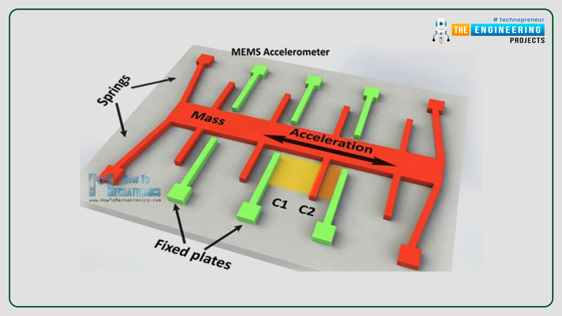
- Accelerometer sensors are integrated circuits (ICs) that are used to measure acceleration, inclination, and various parameters regarding the x,y,z axes. It is the main component to detect the accident.
- Here we used the MEMS (Microelectromechanical Systems) accelerometer. These types of accelerometers are used where we have to measure the vibration or shock without any fixed reference.
- It monitors changes in the capacitance and converts that value to analog output voltage.
- Gyro Range of the Accelerometer sensor is ± 250, 500, 1000, 2000 °/s (may vary depending upon the sensor).
- Accelerometer Range of the sensor module is ± 2 ± 4 ± 8 ± 16 g (may vary depending upon the sensor).
GSM module:
- This module is used to send the notification to the rescue station or the emergency numbers.
- It communicates with the Arduino UNO using the UART protocol.
- It works in a voltage range of 3.5 – 5 volts.
- There are different types of GSM modules available but in this project, we have used the SIM900D module.
- We operate them using the AT commands. As there are hundreds of AT commands but we will use some basic only just to send the message.
Proteus Simulation of Accident Detection Circuit:
Now, it is time to start designing the main circuit of Accident detection in Proteus Simulation software.
- Most importantly, ensure that Proteus is installed on your PC/Laptop and download all the required libraries for Proteus ahead of starting the designing steps.
- For this project, we are going to use libraries for Arduino Uno, GPRS Module, GSM module.
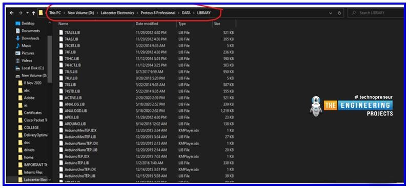
- To add the libraries in the Proteus suite we have to go to the C drive then LabCenter Electronics >> Proteus 8 professional >> Data >> Library and paste the downloaded library files here.
- The download links of all the libraries have been provided to you in the above sections, please go check them out.
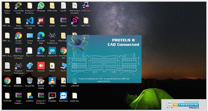
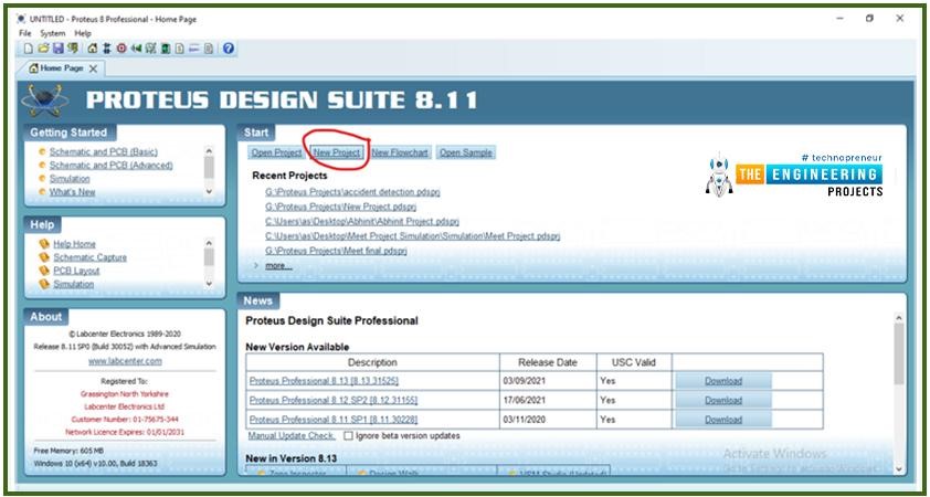
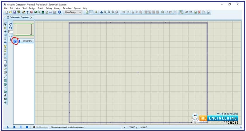
- Let’s start the making of a new project, open the new project in Proteus.
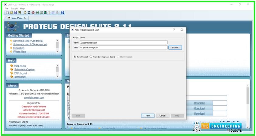
- After that enter the name of your new project.
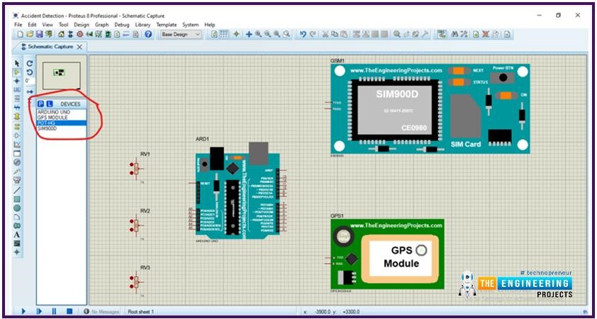
- Now our working area will be open here we will import all the required components which we are going to use.
- The following components need to be selected from the Proteus component library. We’ll connect the components and make the circuit complete.
- Now we have imported all the required components for this project, after this, we will start connecting them.
Circuit Diagram and Working:
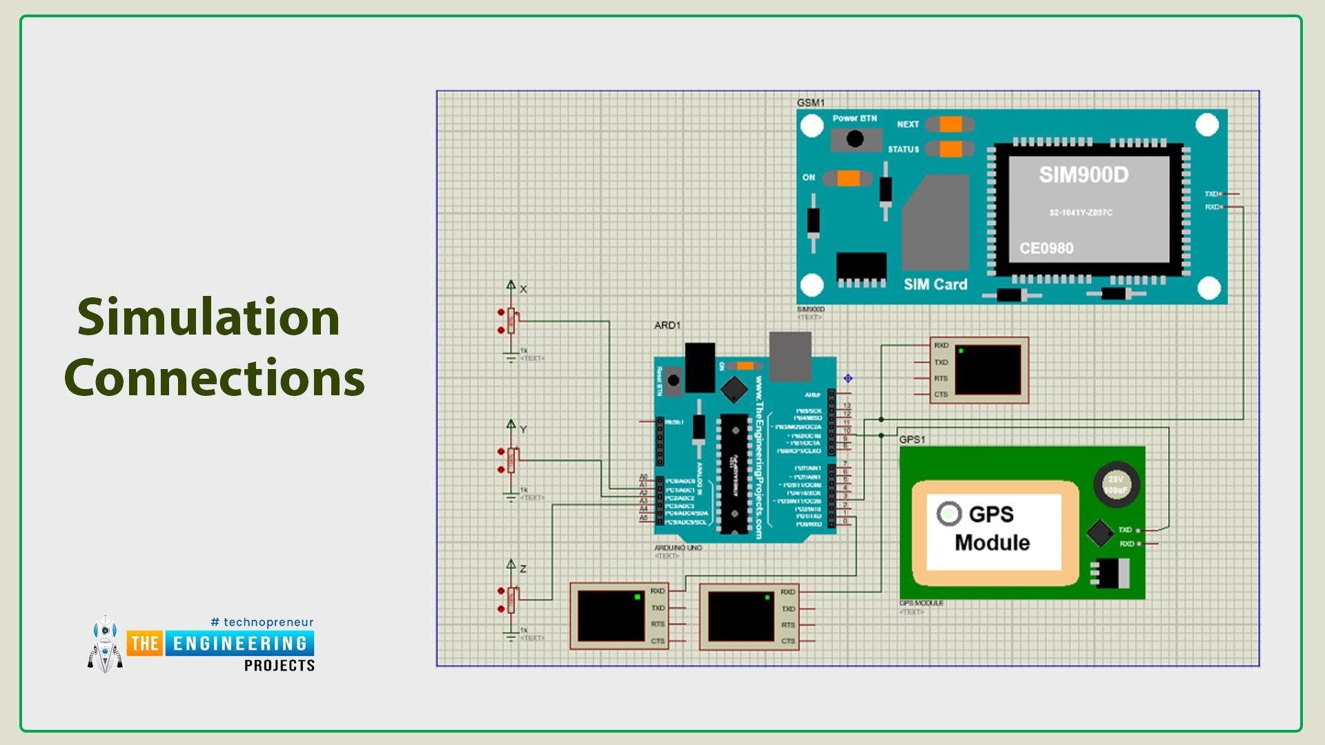
- There are two modules GPRS and GSM modules, both communicate using the UART protocol but in the Arduino UNO there is only one hardware UART’s provision. Now, you may have doubts about how we are going to connect them. No worries, we will handle that on the coding side by declaring the different pins as UART pins.
- We can use different pins for UART using the SoftSerial library of Arduino, which will be discussed in the code.
- We will use the digital pins for UART connections, digital pins 2 and 3 for communication of the GSM module, which means connecting the Rx and Tx of the GSM module with the D2 and D3 pins of Arduino UNO respectively.
- Connect the Rx and Tx of the GPRS module with the D10 and D11 pins of Arduino UNO respectively.
- As modules are connected, now we will connect the accelerometer. As it will not be possible to simulate the accelerometer in Proteus so we have used the potentiometers to change the value of the X-axis, Y-axis and Z-axis.
- You may have doubts about how we can replace the accelerometer with potentiometers. As we will use the MEMS accelerometer, which sends the analog voltages for each axis, so we can simulate that using the potentiometer because we will receive the same type of data.
- We need three potentiometers, one for each axis. Potentiometers of the X-axis, Y-axis and Z-axis will be connected to A1, A2 and A3 pins of Arduino respectively.
- We will connect a serial terminal for debugging purposes.
Arduino code for Accident Detection System
Before going to start the coding, it would be easy if you understood the circuit diagram connections.
- When we start writing the code(called a sketch in Arduino IDE), we will first include all of the necessary libraries for this project.
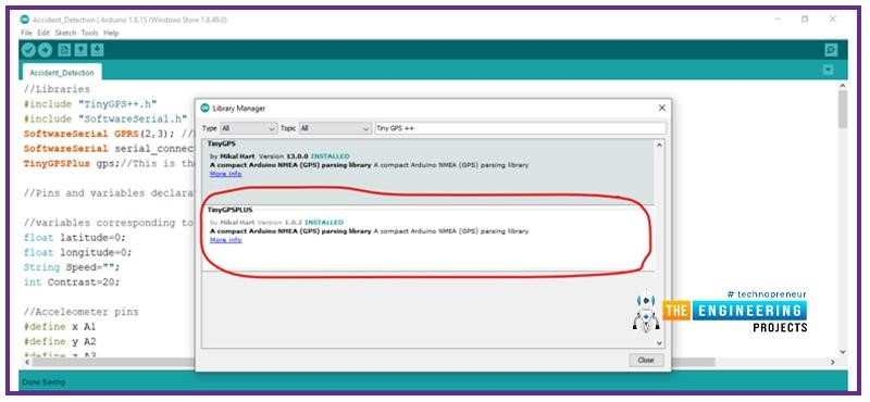
- So, if the essential libraries aren’t already installed in the Arduino IDE, our first step would be to get them.
- Here we use mainly two libraries, one for serial communication and parsing data from the GPS module.
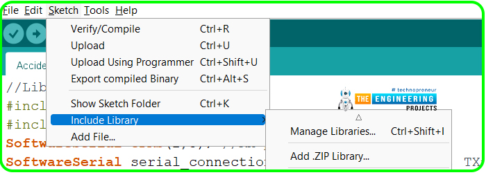
- By heading to ‘Sketch > Include Library > Manage Library’ in the Arduino IDE, we can install libraries related to Arduino. We can now search for our essential libraries in the library manager. We can also use zip files to install the libraries.
- As we’ve installed all the specified libraries. Let’s include them in our sketch.
- Now, we are declaring D2 and D3 pins for serial communication with GPRS modules and declaring GPS objects as well, which will pretty much do all the grunt work with the NMEA data.
- After that, we will declare variables to store the GPS module data.
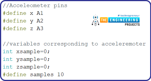
- Now, we are declaring pins and variables for the accelerometer which we will use in our project. Here, we are using Analog Pins because we are reading the analog voltages from the potentiometer.
- We need to declare two threshold values for change in acceleration when an accident is detected.
- The min and max values can vary. So, it is highly recommended to measure the values by accelerometer for devices using.
Void Setup():
- It is one of the most important functions which will execute only once in the whole process.
- As we are using a GPS module in our project, We should first start serial communication between the components and Monitor them through “Serial Monitor” in the Arduino IDE.
- “Serial.begin” is used to set up the serial configuration for the device which is connected to the Serial Port of the Arduino. Here, we will set the baud rate for that device i.e 9600 in our case.
- “serial_connection.begin(9600)” is used to set up the UART configuration for the GPS module. As the GPS module communicates to the Arduino at the baud rate of 9600.
- We are using an Accelerometer in the circuit and it was clearly explained in detail that it will sense the x,y,z coordinates of the device and send them to Arduino.
- Here, we have initialized a for loop to collect the sample data for x, y, and z coordinates of the device in the ideal state.
- Afterward, the sample coordinates have been successfully measured by the Accelerometer sensor, but we need an average value for smoothing the sample coordinate values. So here, we will calculate the average of each coordinate and print them in the serial monitor.
- After the setup, we will write our main application code in the Void loop function.
Void loop():
- It is the second most important function of Arduino code. It will come to action after the execution of “void setup()”
- We’ll write the code required to run in a continuous loop in this part. So this is where we’ll write our primary application code.
- As a result, when the code gets to the void loop portion, We firstly take the NMEA data from the GPS module and print it in the serial monitor.
- Wait a minute, NMEA??, I can understand all the questions in your mind. Let us give you a simple explanation regarding NMEA and its applications.
- The word NMEA stands for the National Marine Electronics Association, which is a mode of communication that existed before inventing GPS. NMEA-format GPS data can be accessed with a wide variety of GPS receivers, instead of creating a new custom interface every time. Thus, it makes our lives easier using the GPS Module.
- When we are printing the NMEA data into the serial monitor, it will be printed in a specific structure. This NMEA data was output from a GPS receiver:
“$GPGGA,191605.00,4521.7785210,N,07331.7656561,W,2,19,1.00,674.354,M,19.900,M,0.90,0000*60”
- All NMEA signals start with the ‘ $ ’ character and for every data field such as coordinates, and various parameters are separated by a comma. The data further includes Timestamp, Latitude, Longitude, Quality indicator, Number of satellites involved, Altitude, etc., which is not necessary to remember. Make sure to get the data from the GPS module. If we have succeeded in this step and get the data on the serial monitor, then we are good to go for further processing.
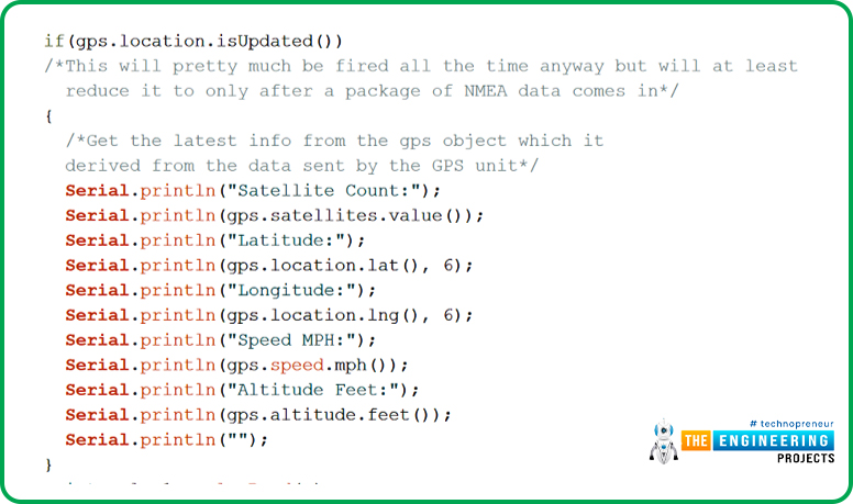
- The “if” statement is to process the NMEA data and separate the data into the required format if there is any location updated to the GPS receiver.
- As we have already received NMEA data in the previous step, the data will be separated into Latitude, Longitude and Altitude.
- In the Loop function, the values of GPS and accelerometer will be continuously tracked.
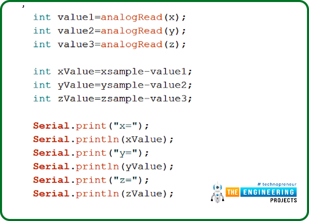
- Here, the analog values of x,y,z coordinates are being measured and printed in the serial monitor.
- These are not the values we measured in the void setup, those were the values to take the readings in the ideal state of the device.
- But in the loop, the values are the present x,y and z coordinates measured by the accelerometer.
- This is the condition for accident detection, we have already discussed before that in the void loop the x,y,z coordinate values are continuously extracted and the “if” statement here compares the recent values with fixed min and max values of the coordinates.
- If the recent values are indistinct or do not match with threshold values i.e., max value and min value, then it indicates that an accident has been detected.
- When the accident detection condition is satisfied, the GPRS module will be activated and will call to rescue stations for aid/help and their home.
- Here, we have programmed to give a call 5 times to the appropriate numbers in the “for” loop.
- And the process also includes a messaging feature along with calling to rescue stations.
- When the same accident condition is satisfied, the messaging feature will be activated and we are going to send the alerting message including the Location, Latitude, Longitude, and Google map location link by appending latitude and longitude values the to respective numbers.
Results / Working:
We have successfully completed our Accident detection project and it’s ready to test!
- Before going to start the simulation, we need to import the hex files of Arduino code in the Proteus, to do so click on the Arduino and browse to the hex file of the code and select.
- Now we need to add the program files for the GPS and GPRS modules.
- Here we should note that we only need to upload the program files for the modules while we are working in simulation. In the real modules, they come up with pre-installed codes.
Now we have done all the prerequisites of simulation.
- Let’s power the circuit and start the simulation, firstly the void setup function will run and it will initialize all the required pins and variables and will read the ideal state values of the potentiometer.
- Now to simulate the accident case, we will change the values from the potentiometer, so when the potentiometer’s value changes and the falls in the Min and Max value range the if condition will be stratified.
- After this GSM module will call the stored number 5 times and send the GPS location with Google maps link in that.
- We have used some serial monitors for debug purposes, you can see the current state of the project using them.
I hope you have a good understanding of how our Accident Detection project works and that you have liked it. Although I believe we have covered almost everything, please let us know if you have any questions or suggestions in the comments section.
Thank you very much for reading this project. All the best for your projects!
JLCPCB – Prototype 10 PCBs for $2 (For Any Color)
China’s Largest PCB Prototype Enterprise, 600,000+ Customers & 10,000+ Online Orders Daily
How to Get PCB Cash Coupon from JLCPCB: https://bit.ly/2GMCH9w
The post Accident Detection System using Arduino appeared first on The Engineering Projects.









No comments:
Post a Comment