
 Bonjour trainees, Welcome to the Engineering projects, We hope your are doing great. We are back with a new experiment. But, during the performance, we’ll also refresh some basic concepts about the topic for best explanation:
- what is shunt clipper?
- what are types of Shunt clippers?
- Implementation of shunt Clippers in Proteus ISIS?
- Dual Clippers and Implementation of Dual Clippers in Proteus ISIS.
basically, this is a connected tutorial from the pervious one that was Series Clippers and its type. if you have concern then you can also check it.
for now, let’s get to the 1st Question.
1.What is shunt clipper?
The very basic definition of shunt clippers is given below:
“A type of clippers in which the diode is connected in Shunt ( Parallel) to the input signal source and as output we get diminished wave , according to the type of shunt Clippers , is called Shunt Clipper (parallel Clippers).“
Shunt Clippers are extremely useful in many circuits and engineers use it in different ways.
We can get a definitive concept by its types.
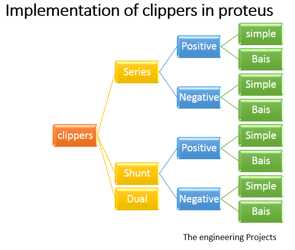
2.What are types of Shunt clippers:
Shunt clippers are Classified into many types. We’ll discuss the following types:
- Positive
- Positive with bias
- Negative
- Negative with bias
I will execute all of these types one after the other in the Proteus.
Implementation of shunt Clippers in Proteus ISIS:
for the implementation, get the Proteus circuit start it, and follow the steps:
Apparatus required:
- Vsine
- Diode
- Resistor
- Ground terminal
- Oscilloscope
- Choose the first three components from the “Pick library” by mere writing the required component’s name.
- Set the components at the working area.
- Left click on the screen go to >place>Terminal>Ground and fix it on the place.
- Get the Oscilloscope from the “Virtual Instrument Mood” in the left most bar and fix it at the side of circuit.
Positive Shunt Clippers:
In positive Shunt clippers we connect the Diode parallel to the load resistance. The input signal source passes signal to the load resistance when the diode is reverse bias and the vise versa.
- Set the diode in a way that the arrowhead of diode points opposite to the input source and assume that the current is entering to the positive side of diode.
- Connect all the apparatus according to the circuit:
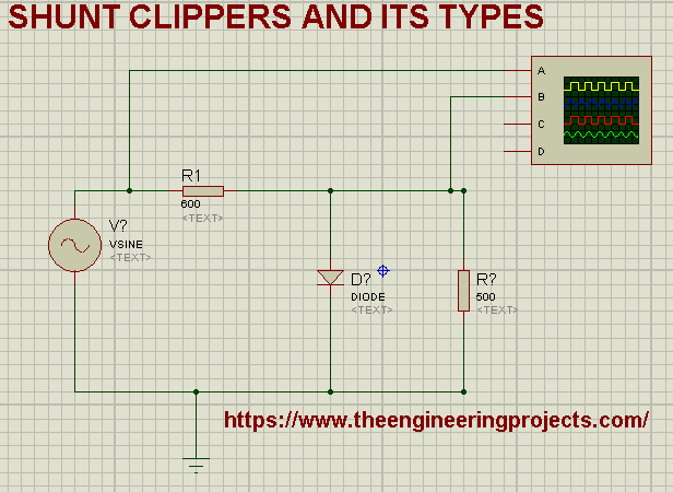
- Change the values of components according to the below table:
| Components | Value |
| Resistor R1 | 600 ohm |
| Resistor R2 | 500 ohm |
| Vsine | Amplitude =110V,Frequency= 1000Hz |
| Oscilloscope | Time= 0.2m-1,Voltage 20V |
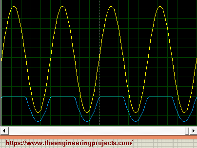
- When you will done all the efforts, you will definitely acquire the required output as:
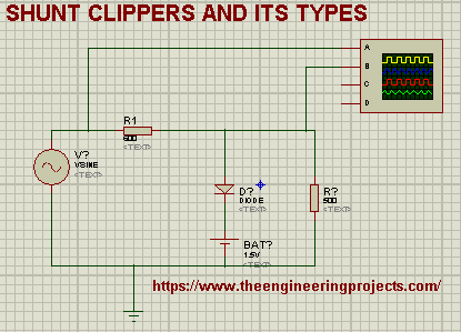
Positive with bias:
When we add the battery in the circuit of positive shunt clippers in a specialized manner, we get the Positive Shunt Clippers with bias or Biased positive clippers.
There are two kinds of biased circuit:
- Positive bias
- negative bias
To make positive bias Shunt clipper just follow the instruction:
- Add the battery just after the diode in the circuit such that the Positive Terminal of battery connects with diode’s arrowhead and negative terminal is attached with the vsine source.
- The circuit will peep like this:
NOTE: you will learn about the negative biased arrangement in upcoming circuit.
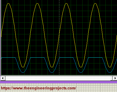
When I played the Circuit, the the output with same values is shown as:
Negative Shunt Clippers:
“The circuit in which we connect the diode Parallel to the AC source in such a manner that the arrowhead of the diode points the AC source is called Negative Shunt Clippers.”
In the circuit we are working for just revert the direction of diode and arrange all the components on the Proteus ISIS working screen according to the given circuit:
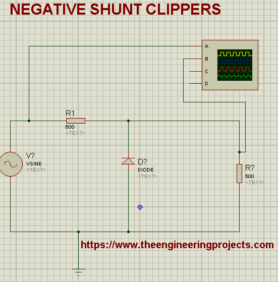
In this arrangement, the diode passes the signal during the positive half cycle the diode is reversed bias so that we get the positive half cycle, contrary to this, in negative cycle duration the diode does not allow the current to pass through it.
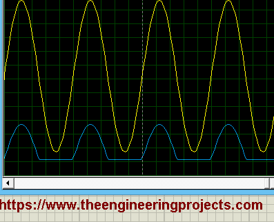
Therefore, as output of Oscilloscope, we get the following form of wave:
Biased Negative Shunt Clippers:
“We call a circuit as Biased Negative Shunt Clippers when we add a battery (Either in positive or negative manner) to the circuit of Negative Shunt Clippers.”
Hence add the battery from the Picked components of the Proteus.
Fasten the Battery with the diode in such a way that the negative terminal of battery connects the diode and positive terminal of battery connects to the vsine source.
Let’s rush towards the next Question.
4.Dual Clipper and their Implementation in Proteus ISIS:
As the name Depicts, the Dual clippers is the combination of two types and may be defined as:
“A Dual clipper is the amalgamation of two types of Shunt Clippers called Biased Shunt Positive Clippers and Biased Shunt negative clippers.”
Now, let’s move towards its experiment.
- Change the name of both Resistors as R1 and R2 (or any desired name) to discriminate them.
- By the same token, Substitute the name of both Diodes as D1 and D2 (or any desired name) as well.
- For the formation of such clippers we will add both the arrangements according to the circuit given:
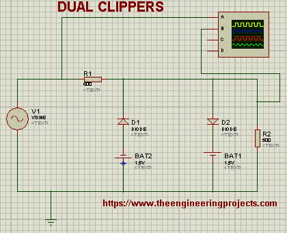
You can clearly see that the circuit contain both types of arrangements so we expect the combination output wave of both types of circuit.
- For better visualization, I have set the channel B to 2V.
- Pop the Play button, and have a look at the output:
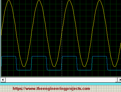
One can see that we got a square wave that conducts the current in both direction but in in clipped form. We need Dual clippers in the place where we need to clip some part of both sides of sinusoidal wave of the output.
So, that’s all for today. In this article we find out that what are Shunt clippers, what are the types and implementation. We also learnt Dual Clippers along with their implementation in Proteus ISIS.
JLCPCB – Prototype 10 PCBs for $2 (For Any Color)
China’s Largest PCB Prototype Enterprise, 600,000+ Customers & 10,000+ Online Orders Daily
How to Get PCB Cash Coupon from JLCPCB: https://bit.ly/2GMCH9w
The post Shunt Clippers and Dual Clippers in Proteus ISIS appeared first on The Engineering Projects.
No comments:
Post a Comment