
Hey buddies, Hope you are fine. We are here with a new tutorial of Proteus. Before this, we tough you about Half Wave Rectification.
In this article, We will perform the experiment of Full Wave recertification through bridge rectifier in the Proteus by making the circuit that is almost identical to the real-life experiment as all the components and working is similar.
This can also be called as full wave rectification through bridge rectifier.
For better conception, this article also includes two little points:
- What is full wave rectification
- What are the advantages of Full Wave Rectification over Half Wave Rectification.
Let’s Comprehend the 1st Question.
1.What is full wave rectification
A comprehensive definition of full wave rectification is:
“Full-wave rectification is the process to converts both polarities of input (sinusoidal)wave to pulsating DC (Direct current).”
Revise the concept that the current in our houses is in the form of Alternating current. It has a full cycle. So, we need to convert it in the form of direct current in some cases.
Hence, the device used for this purpose is full wave rectifier and the process is called full wave rectification.
Let’s jump to the 2nd Question and find the answer.
2.Advantages of FULL WAVE RECTIFICATION
If you have learnt or heard about the Half wave rectification, then there must be a query in your mind that why there is a need of full wave rectification if we have a basic, simple and working circuit of half wave rectification.
If you have this, then you are really a good learner and I am here to solve the question.
As we all know a diode can pass the electricity through it on in one half cycle. So we can use more than one diode and use it in many ways.
Some of advantages of full wave rectification over half wave rectification are:
- During half wave rectification, half of the wave is wasted as diode can only work during 1 half cycle. But if we add the bridge (or another diode) then during the 2nd half cycle (that was stopped in the diode) the output will be accessed and we get the full half cycle in the ideal situation.
- .Higher output voltage.
- Low ripple factor.
One can get smooth waveform by using the ripple frequency can be obtained.
Practical performance of FWR in Proteus ISIS:
In Proteus, we can make the desired circuit easily as it has all the components and functionality.
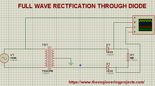
For a concept, it will be useful to know that the bridge has four corners out of which one is called anode, 2nd is called cathode and left and right corner has the output.
So, let’s move towards its construction.
- First of all, we have to pick the components we need for the experiment.
- For a start, we need three basic components:
- Full Wave rectification bridge
- Resistor
- Alternating voltage source
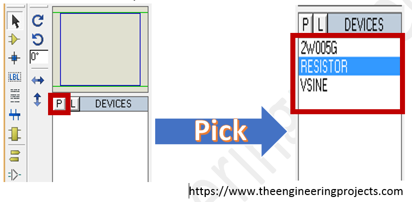
- Go to the pick library button situated in the left of screen having the button with symbol “P”.
- In our case, we are going to suppose the upper as Anode and lower as Cathode. Being the sinusoidal wave, it changes its direction at regular interval.
- For this, Choose the ingredients one by one from the pick library by clicking them and then double click the working screen and fix them. To allow the current flow from the circuit, we are supposed to connect all the components. This can be done only with wires.
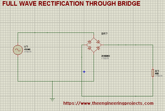
- To pick the ground terminals, there are more then one way. Hence tap the right button, go to place> Terminal>Ground and add it to the wire connected directly to the anode (assumed) of the bridge.
- Change the value of rectification to 500 ohm by simply double clicking and giving the value.
- Click at the ends of the components and connect them according to the circuit given below:
Now we are moving towards Settings the values of components. At this instance, we are supposed to add some other components from other portions. So that we can get the output. We need an Oscilloscope that is an output device and a ground terminal to limit the voltages that can appear on distribution circuits.
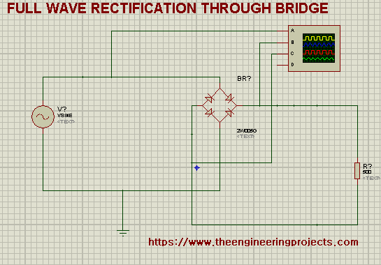
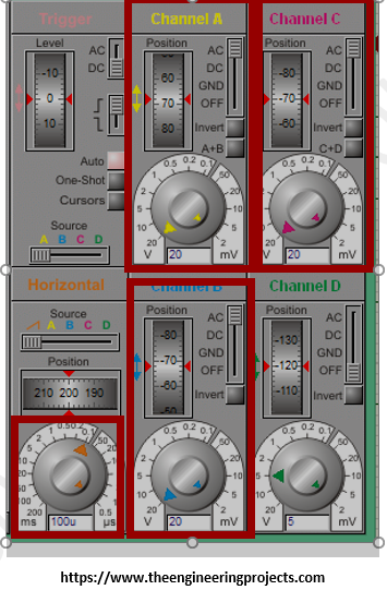
- Choose the oscilloscope from the Virtual instruments’ mood> Oscilloscope. Fix it in the place where we can connect it with the circuit. Connect Terminal A before the bridge, terminal B with right output of the bridge and terminal C with the left output of the bridge so that we can see the input and output wave at the same time.
- Now our Circuit should look like the picture below:
- There is a need of setting the values of components and we are going to do this one by one.
- Double tap the mouse left button on the vsine source and change the values according to need. we are going to give frequency of 1000Hz and amplitude of 120V.
These values vary according to the type of components used, the value of frequency and amplitude of the sinusoidal wave source and some other factors. We got the output. The Yellow (A Terminal) wave shows the input that is sinusoidal wave. Whereas, the blue wave (B terminal) shows positive half cycle and magenta one (C terminal) shows the negative half cycle. And the magic is, both the outputs are direct current but we are getting full wave as the combination.
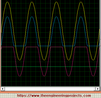
In this way we get the result of two waves that gives us the full wave rectifier as aggregated effect.
Thus, today we learnt another simple Proteus experiment that shows what is full wave rectification, how to make the simplest circuit that shows the best output of full wave rectification and why we need the full wave rectification circuit.
JLCPCB – Prototype 10 PCBs for $2 (For Any Color)
China’s Largest PCB Prototype Enterprise, 600,000+ Customers & 10,000+ Online Orders Daily
How to Get PCB Cash Coupon from JLCPCB: https://bit.ly/2GMCH9w
The post Full Wave Rectification in Proteus appeared first on The Engineering Projects.
No comments:
Post a Comment