Hello readers, I hope you all are doing great. In this tutorial, we will learn how to interface the BMP280 sensor with the ES32 module to get temperature, pressure and altitude readings. Later, in this tutorial, we will also discuss how to upload these sensor readings to a web server.
BMP280
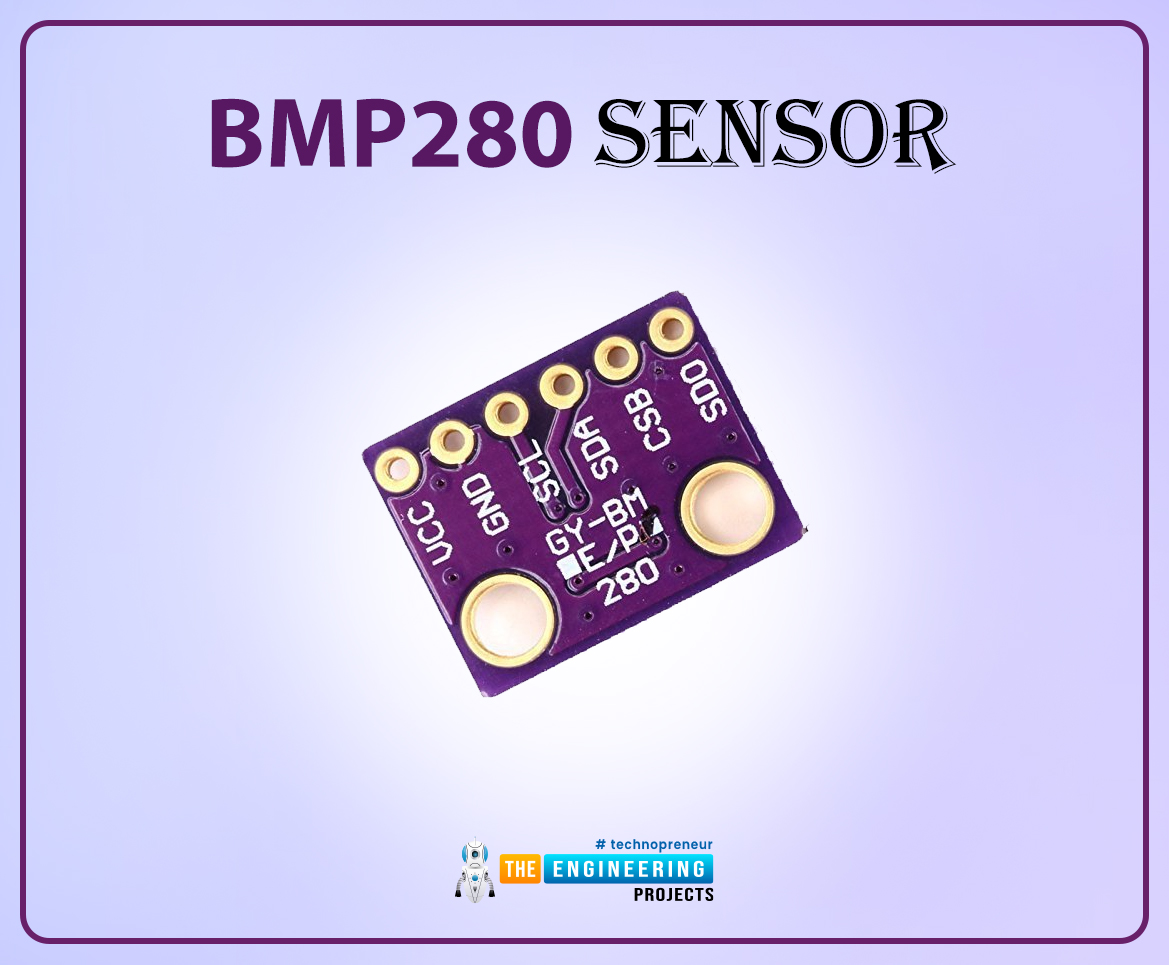
BMP280 or Barometric pressure sensor is a module used to measure temperature pressure and altitude. The small size and low power consumption feature of this sensor makes it feasible for battery-powered devices, GPS modules and mobile applications etc.
Fig. 1 BMP280 Sensor
The BMP280 is the product of BOSCH which is based on Bosch’s proven Piezo-resistive pressure sensor technology featured with high accuracy, long term stability, linearity and high EMC robustness.
BMP280 is the successor of the BMP180 sensor and offers high performance in all the areas that require precise temperature and pressure measurements.
Emerging applications like fitness, indoor navigation, GPS refinement requires relative accuracy and BMP280 is perfect for such applications. Very low TCO (Temperature coefficient of Offset ) makes this module preferable over other available modules for temperature measurements.
We can also use a DHT11/DHT22 sensor for temperature and humidity measurements but the BMP280 sensor provides better accuracy (i.e., 0.01˚C) than DHT sensors.
Technical specifications of BMP280
- Operating voltage: 1.8 -3.3V DC
- Communication protocols supported: SPI, I2C
- Ultra low power consumption
- Temperature accuracy: 1˚C
- Temperature range: -40 to 85˚C
- Absolute accuracy : 1 hPa
Components required:
- ESP32 development board
- Arduino IDE for programming
- BMP280 sensor
- Breadboard
- Connecting wires
Interfacing BMP280 with ESP32
There are two methods of interfacing BMP280 sensor with ESP32 module:
- I2C protocol
- SPI protocol
In the bMP280 Sensor module, there are six interfacing pins including VCC and GND.
Fig. Interfacing BMP280 and ESP32
We are using the I2C protocol for interfacing the two (ESP and BMP280) so only SCL and SDA pins will be used with power pins for interfacing. The SDO and CSB pins will be used only if you are using the SPI protocol for interfacing.
Table 1
Programming with Arduino IDE
We are using Arduino IDE to compile and upload code into the ESP32 module. You must have ESP32 board manager installed on your Arduino IDE to program the ESP32 module. To know more about Arduino IDE and how to use it, follow our previous tutorial i.e., on ESP32 programming series. The link is given below:
https://www.theengineeringprojects.com/2021/11/introduction-to-esp32-programming-series.html
Steps to add the necessary libraries in Arduino IDE:
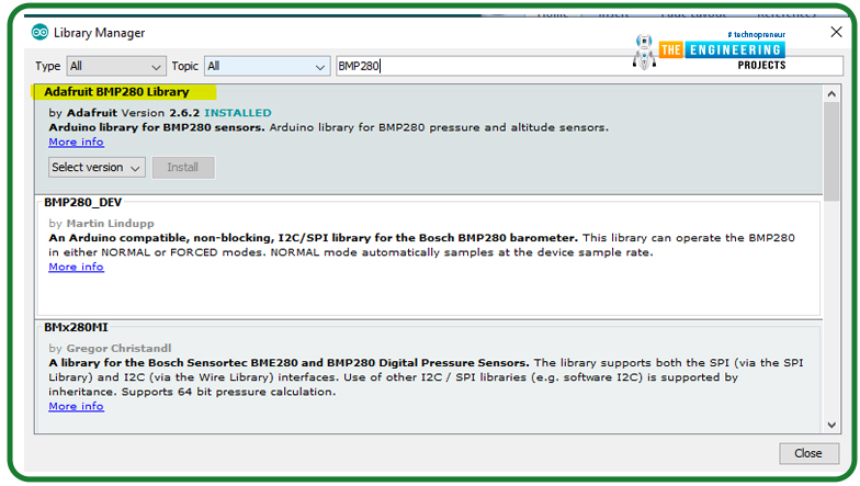
- Go to Tools >> Manage Libraries.
Fig. 2 manage libraries
- Search for the Adafruit BMP280 library in Library Manager and click Install.
Fig. 3 Install library
Getting I2C address
- In order to interface your ESP32 with BMP280, you should know the I2C address of the sensor (BMP280).
- To obtain the address of the I2C device, copy and paste the below attached code into your Arduino IDE.
- Compile and upload the code.
- Open the serial monitor at 115200 baud rate.
- Now you should see the address of your I2C device printed on the serial monitor.
- Copy the I2C address and paste in your final code (interfacing esp32 and BMP290 sensor).
#include <Wire.h>
void setup()
{
Wire.begin();
Serial.begin(115200);
Serial.println(“\nI2C Scanner”);
}
void loop()
{
byte error, address;
int nDevices;
Serial.println(“Scanning…”);
nDevices = 0;
for(address = 1; address < 127; address++ )
{
Wire.beginTransmission(address);
error = Wire.endTransmission();
if (error == 0)
{
Serial.print(“I2C device found at address 0x”);
if (address<16)
{
Serial.print(“0”);
}
Serial.println(address,HEX);
nDevices++;
}
else if (error==4)
{
Serial.print(“Unknow error at address 0x”);
if (address<16) {
Serial.print(“0”);
}
Serial.println(address,HEX);
}
}
if (nDevices == 0) {
Serial.println(“No I2C devices found\n”);
}
else {
Serial.println(“done\n”);
}
delay(5000);
}
Code (Interfacing and fetching sensor reading from BMP280 with ESP32)
#include <Wire.h>
#include <Adafruit_BMP280.h>
#define BMP_SDA 21
#define BMP_SCL 22
Adafruit_BMP280 bmp280;
void setup()
{
Serial.begin(115200);
Serial.println(“Initializing BMP280”);
boolean status = bmp280.begin(0x76);
if (!status)
{
Serial.println(“Not connected”);
}
}
void loop()
{
float temp = bmp280.readTemperature();
Serial.print(“temperature: “);
Serial.print(temp);
Serial.println(“*C”);
float altitude = bmp280.readAltitude(1011.18);
Serial.print(“Altitude: “);
Serial.print(altitude);
Serial.println(“m”);
float pressure = (bmp280.readPressure()/100);
Serial.print(“Pressure: “);
Serial.print(pressure);
Serial.println(“hPa”);
Serial.println(” “);
delay(1000);
}
Code Description
- The first task is adding necessary header files.
- We are using two libraries:
- The Wire.h is used to enable I2C communication/interfacing.
- The second library we are using is, Adafruit_BMP280.h is to control the BMP sensor and access its respective function.
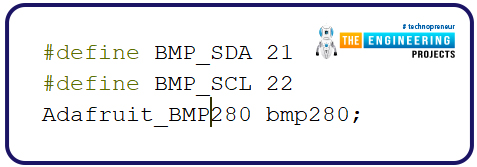
- As we mentioned earlier, we are using the I2C protocol for interfacing BMP280 with ESP32. So we need to define the I2C GPIO pins.
- In the ESP32 DevKit V1 development board, the GPIO_21 and GPIO_22 are the SDA and SCL pins for I2C communication.
- Then a bmp280 object is declared for interfacing the sensor.
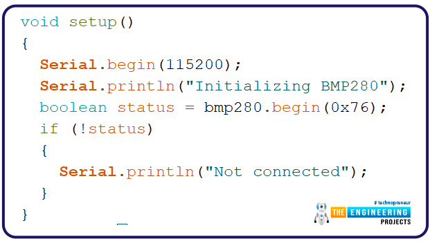
Setup()
- In the setup() function, we are initializing the serial communication at 115200 baud rate for debugging purposes.
- The BMP280 sensor is initialized with bmp280.begin() function where we are passing the I2C address of the module as an argument.
- Next, we need to check the status of the interface and the respective result will be printed on the serial monitor.
Fig. 6
Loop()
- The next task is getting the sensor readings.
- Here we are measuring three parameters, temperature, humidity and altitude.
- A float type variable “temp” is defined to store the temperature readings observed from BMP280 sensor using readTemperature() function.
Fig. 7
- Next, the altitude is measured using bmp280.readAltitude function.
- We need to adjust the altitude to the local forecast using the multiplying factor.
Fig. 8
- The bmp280.readPressure() function is used to obtain the pressure using BMP280 sensor.
- BMP280 sensor readings will be updated every time with a delay of 1 second.
Fig. 9
Testing
- Open your Arduino IDE and paste the above code.
- Compile and upload the code into ESP32 development board.
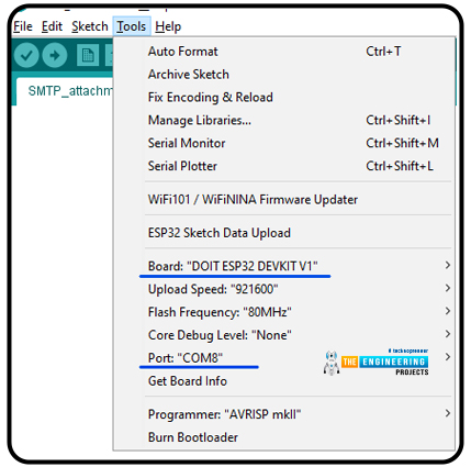
- Before uploading the code make sure that you have selected the correct development board and COM port.
Fig. 10 Select development board and COM port
- Once the code is uploaded successfully, open the Serial monitor and select the 1115200 baud rate (as per your code instructions).
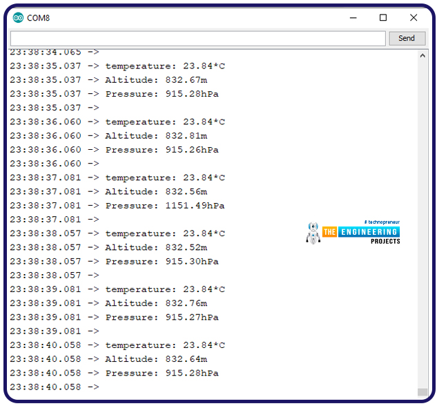
- Now you should see the readings obtained from barometric pressure sensor.
Fig. 11 Serial monitor output
Uploading BMP280 Sensor data to ThingSpeak server
Most of the industries and organizations these days are shifting to the efficient ways of operating things and the IoT internet of things is one of them.
Internet of Things is a system of multiple inter-related computing devices. The factor ‘thing’ in IoT is designated to an entity capable of communicating data over a network (IOT), which can be a digital machine, sensor, human being, animals etc.
Each component that is included in IoT network is assigned with an unique identity called UID and the ability to communicate data over IoT network without any external human or computer intervention.
Fig. 12 IoT
ThingSpeak is an open data platform for the Internet of Things applications. It is a MathWorks web service that allows users to send sensor readings and data to the cloud. We can also visualize and act on the data (calculate the data) that is sent to ThingSpeak by the devices. The information can be saved in both private and public channels.
ThingSpeak is frequently used for IoT prototyping and proof-of-concept devices that require data analysis.
Programming with Arduino IDE
Downloading and installing the required Library file:
- Follow the link attached below to download the thingSpeak Arduino library:
https://github.com/mathworks/thingspeak-arduino
- Open the Arduino IDE.
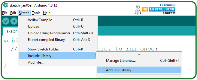
- Go to Sketch >> Include Library >> Add .ZIP Library and select the downloaded zip file.
Fig. 13 Adding ThingSpeak library
To check whether the library is successfully added or not:
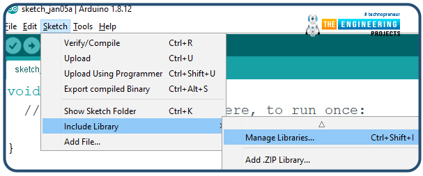
- Go to Sketch >> Include Library >> Manage Libraries
Fig. 14
- Type thingspeak in the search bar.
Fig, 15 Arduino IDE Library manager
- The ThingSpeak library by MathWorks has been successfully downloaded.
Getting Started with ThingSpeak
- To create and account or log in to ThingSpeak (operated by MathWorks) server follow the link: https://thingspeak.com/
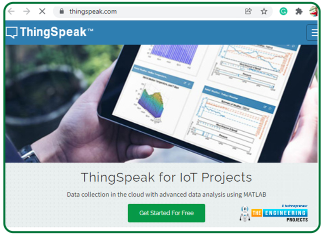
- Click on Get Started for free.
Fig. 16 Getting started for free
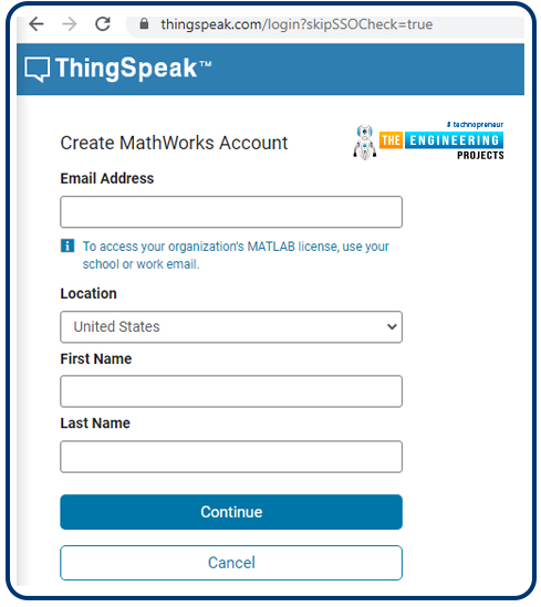
- Enter the required details to create a MathWorks account as shown below:
Fig. 17 Create new account
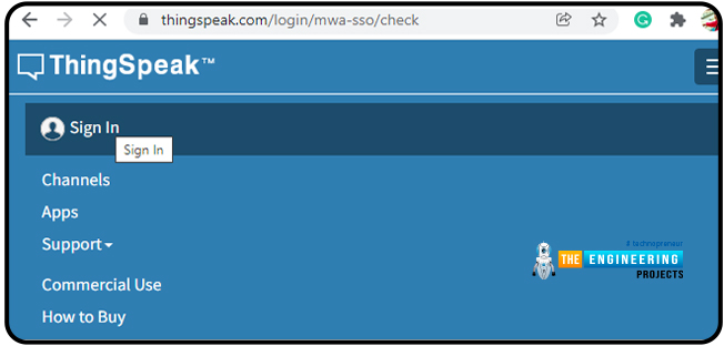
- If you have already created a MathWorks account, then click on Sign in.
Fig. 18 MathWorks Sign in
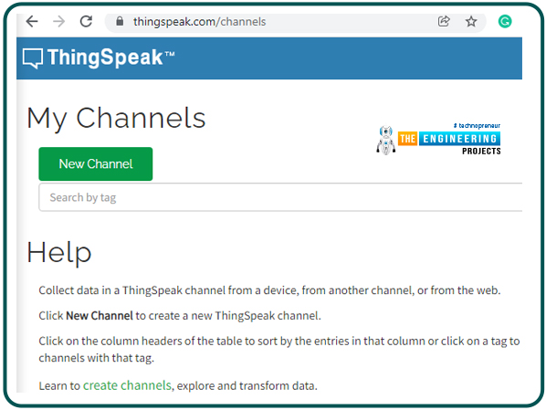
- Create a channel by clicking on the New Channel
Fig. 19 New Channel
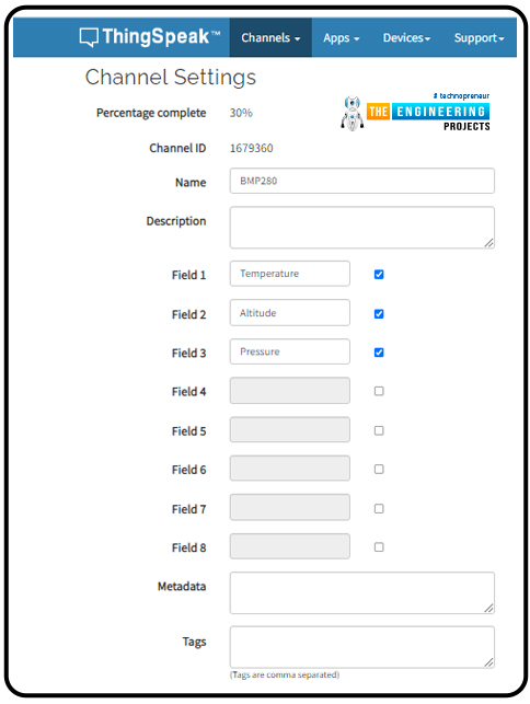
- Enter the respective details in the channel.
- Because we are measuring three parameters (temperature, pressure and altitude), hence we need to create three different fields in this channel.
Fig. 20 Creating channel and respective fields
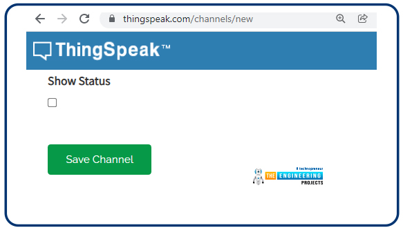
- Press “save” button.
Fig. 21 save the channel
- After successfully saving the channel, a new window will open containing the channel details and Channel Stats.
- In the same window, go to API Keys which contains the Write API keys and Read API keys.
- Copy the Write API key and paste this in ESP32 Arduino code to upload the sensor readings on ThingSpeak server.
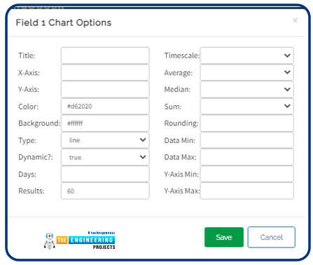
- You can also customize the chart in Private View. Click on the icon present at the top right menu of Field Chart (in red box) to edit the chart.
- Edit the details as per your requirements and click on save button to save the details.
Fig. 22 Field Chart Edit
- Now your ThingSpeak channel is ready to communicate and save/store data.
Code (Arduino IDE)
// ——style guard —-
#ifdef __cplusplus
extern “C”
{
#endif
uint8_t temprature_sens_read();
#ifdef __cplusplus
}
#endif
uint8_t temprature_sens_read();
// ——header files—-
#include <WiFi.h>
#include “ThingSpeak.h”
#include <Wire.h>
#include <Adafruit_BMP280.h>
#define BMP_SDA 21
#define BMP_SCL 22
Adafruit_BMP280 bmp280;
// —–netwrok credentials
const char* ssid = “public”; // your network SSID (name)
const char* password = “ESP32@123”; // your network password
WiFiClient client;
// —–ThingSpeak channel details
unsigned long myChannelNumber = 4;
const char * myWriteAPIKey = “9R3JZEVBG73YE8BY”;
// —– Timer variables
unsigned long lastTime = 0;
unsigned long timerDelay = 1000;
void setup()
{
Serial.begin(115200); // Initialize serial
Serial.println(“Initializing BMP280”);
boolean status = bmp280.begin(0x76);
if (!status)
{
Serial.println(“Not connected”);
}
//Initialize Wi-Fi
WiFi.begin(ssid, password);
Serial.print(“Connecting to Wi-Fi”);
while (WiFi.status() != WL_CONNECTED)
{
Serial.print(“.”);
delay(100);
}
Serial.println();
Serial.print(“Connected with IP: “);
Serial.println(WiFi.localIP());
Serial.println();
// Initialize ThingSpeak
ThingSpeak.begin(client);
}
void loop()
{
if ((millis() – lastTime) > timerDelay )
{
float temp = bmp280.readTemperature(); //temperature measurement
Serial.print(“temperature: “);
Serial.print(temp);
Serial.println(“*C”);
float altitude = bmp280.readAltitude(1011.18); //altitude measurement
Serial.print(“Altitude: “);
Serial.print(altitude);
Serial.println(“m”);
float pressure = (bmp280.readPressure()/100); //pressure measurement
Serial.print(“Pressure: “);
Serial.print(pressure);
Serial.println(“hPa”);
Serial.println(” “);
ThingSpeak.setField(1, temp );
ThingSpeak.setField(2, altitude);
ThingSpeak.setField(3, pressure);
// Write to ThingSpeak. There are up to 8 fields in a channel, allowing you to store up to 8 different
// pieces of information in a channel. Here, we write to field 1.
int x = ThingSpeak.writeFields(myChannelNumber,
myWriteAPIKey );
if(x == 200)
{
Serial.println(“Channel update successful.” );
}
else
{
Serial.println(“Problem updating channel. HTTP error code ” + String(x) );
}
lastTime = millis();
}
}
Code Description
We are describing only the ThingSpeak server part as the BMP280 and ESP32 interfacing part has already been discussed in the above code description.
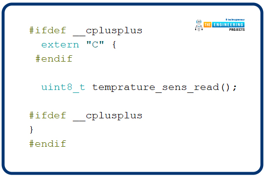
- The style guard is used at the beginning to declare some function to be of “C” linkage, instead of “C++”
- Basically, it allows the C++ code to interface with C code.
Fig. 23 Style guard
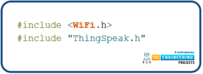
- Add the necessary header/library files.
- We have already discussed above how to download and add the ThingSpeak library file to Arduino IDE.
Fig. 24 Libraries
- Enter the network credentials (SSID and Password).
Fig. 25
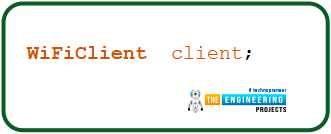
- A Wi-Fi client is created to connect with ThingSpeak.
Fig. 26
- Define timer variables.
Fig. 27
- Add the channel number and API (Write) Key. If you have created only one channel then the channel number will be ‘1’.
Fig. 28
Setup()
-
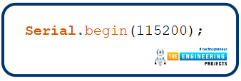
- Initialize the Serial monitor with a 115200 baud rate for debugging purposes.
Fig. 29
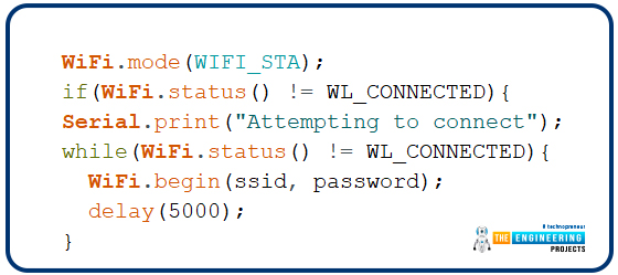
- Set ESP32 Wi-Fi module in station mode using mode() function.
- Enable ESP32’s Wi-Fi module using begin() function which is using SSID and password as arguments.
- Wait until the ESP32 is not connected with the wifi network.
Fig. 30
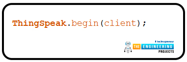
- Initialize the ThingSpeak server using begin() function that is passing client (globally created) as an argument.
Fig. 31
Loop()
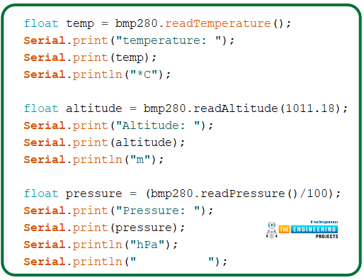
- We are defining three float type variables to save temperature, altitude and pressure measurements respectively.
Fig. 32 Sensor readings
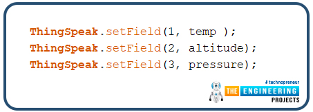
- Setting up the ThingSpeak fields for respective sensor measurement. The various sensor readings are passed as arguments inside the ThingSpeak.setField() function with there respective filed number.
Fig. 33 setting respective Fields
- writeFields() function is used to write data to the ThingSpeak server. This function is using the channel number and API key as an argument.
Fig. 34
- Return the code 200 if the sensor readings are successfully published to ThingSpeak server and print the respective results on the serial monitor.
Fig. 35
Results
- Open your Arduino IDE and paste the above code.
- Compile and upload the code into the ESP32 development board.
- Before uploading the code make sure that you have selected the correct development board and COM port.
- Make sure the Wi-Fi network to which your ESP device is supposed to connect is active.
- Open the serial monitor at a 115200 baud rate and press the EN button from ESP32 development.
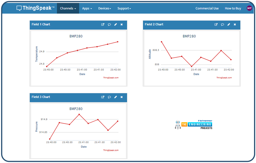
- Once your ESP32 is connected with the wi-fi network, open the channel you have created on the ThingSpeak server.
- Now you see the sensor readings displayed on their respective fields.
Fig. 36 ThingSpeak server
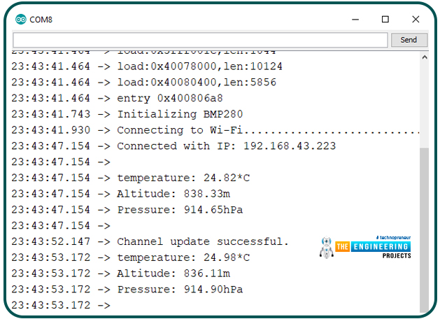
- You can also compare the data displayed on the server with the serial monitor.
Fig. 37 Sensor readings on the Serial monitor
This concludes the tutorial. I hope you found this of some help and also hope to see you soon with a new tutorial on ESP32.
JLCPCB – Prototype 10 PCBs for $2 (For Any Color)
China’s Largest PCB Prototype Enterprise, 600,000+ Customers & 10,000+ Online Orders Daily
How to Get PCB Cash Coupon from JLCPCB: https://bit.ly/2GMCH9w
The post ESP32 BMP280 sensor Interfacing with ThingSpeak WebServer appeared first on The Engineering Projects.












No comments:
Post a Comment