The greatest idea here is for us to have useful knowledge on matters PCB. That before we talk about mounting methods, we still need to remind ourselves of what PCBs are, their importance, what are the new trends and many other relevant information. Just a quick reminder, when we talk about PCBs, we are focusing on signal processing. To do signal processing, there must be electricity, and also there must be electrical components either active for example the current source and passive for example the resistor. The process of signal processing will involve arranging of electrical components in a particular order, allowing regulated electric current to pass through it. This component plus the electric current forms what we call the electrical circuit, the circuit is also labeled as the electrical schematics.
In the beginning, a breadboard was used to hold the schematic together. This had a major disadvantage because components could pull out hence giving hard times to the designers especially if the circuitry was so complex. Therefore, the mounting of the components was not that firm and secure. Today breadboards have been reduced into testing and prototyping tools.

In this article, we are going to have a look at the surface mount technology which is currently the most used component mounting method.
Introduction to Surface Mount Technology
Overview
This is another method that is involved in the process of PCB manufacturing for the mounting of the components.
- Also known as planner mounting.
- Its discovery came in the 1980s when companies were struggling with the high demand for printed circuit boards. Fab houses had started shifting to mass production of the boards and therefore they had to introduce new methods of PCB assembly and mounting to speed up the process. SMT was one of the methods that were introduced.
- This is the most popular method that is being employed in today’s PCB manufacturing process because it can be purely automated hence increasing the amount of the boards produced and also saving on production time. With this method, the cost of the PCBs was reduced drastically.
- As you can hear from the name suggests, the components are mounted on the surface. There are no holes for the mounting of the components like in the THT method.
- Initially, the process was done manually but today it is done by the use of advanced machinery thanks to the technology revolution that has taken place.
SMT Definition
Surface mount technology involves a very critical process where components are mounted on the surface of the board instead of them being mounted through the holes as the names suggest. The components are then soldered by the assembler onto pads and boards.
How to place an SMT PCB order?
There are many online PCB companies available, where we can place orders for PCB having SMT components. Let’s take the example of JLCPCB Fabrication House, one of the leading PCB manufacturers and offers top-quality product.
- First of all, open this JLCPCB SMT Assembly Page.
- Here you can see, it’s quite easy to place the SMT order.
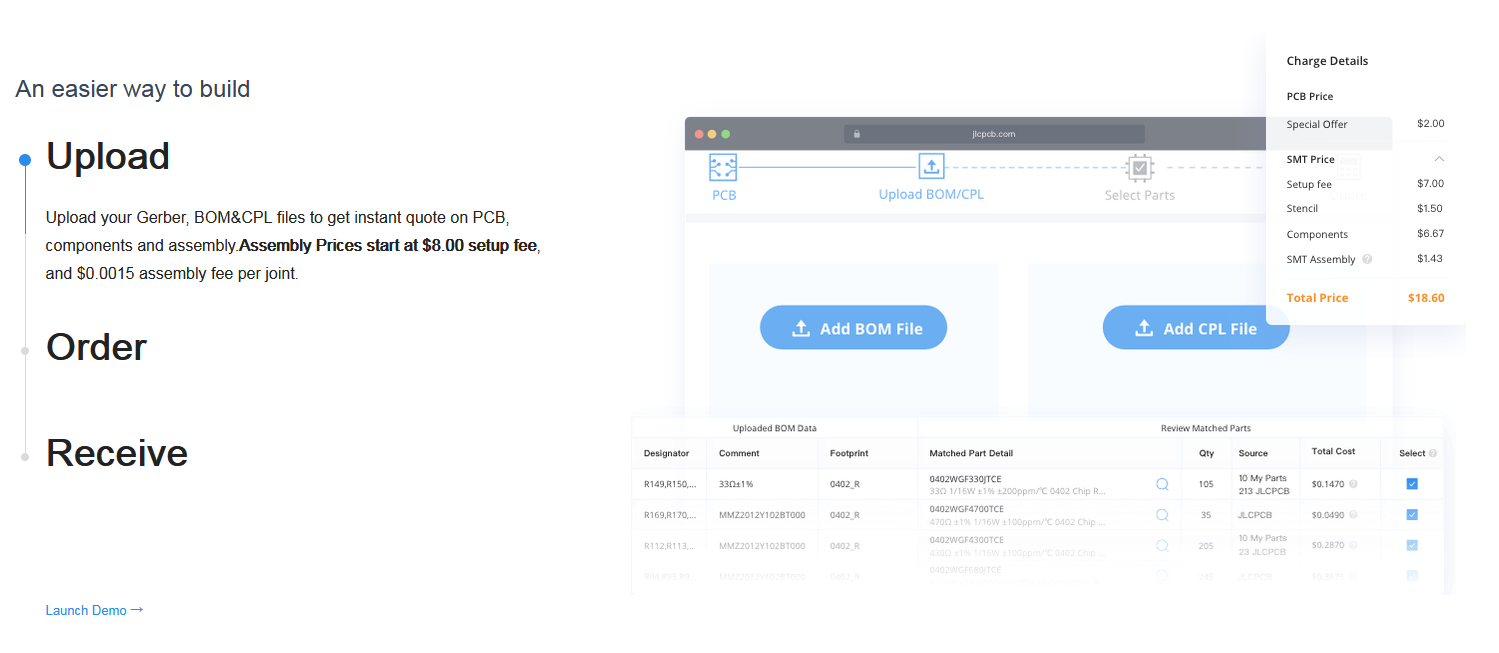
- First, you need to Upload the PCB Gerber Files, as shown in the below figure:
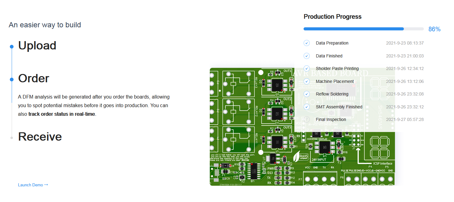
- JLCPCB has a remarkable online PCB order tracking system, which keeps you aware of the current situation of your PCB order, shown in the below figure:
- Once your SMT PCB order gets completed, you will receive it at your doorstep.
SMT Process
- Using the assembler, you apply the solder pastes into the parts where the components will be placed. The solder paste placement follows the guidelines from the design.
- Use the stencil or the solder screen to ensure that the solders have been placed in the exact required position for the component placement. Stencils will follow what is in the client’s design before concluding that the soldering has been done the right was as it should.
- After that, inspect the board to check for the solder defects and ensure that all the solders are in good position. Sometime stencils and assemblers might not be that accurate and as an operator, you have a duty to inspect the solder to ensure that it has met the required standards.
- Any time you detect the defects, it is either the assembler corrects the defects or if they are too much the assembler will remove them and reapply afresh.
- The process of inspection is very important because it will determine the quality of the solder during the end of the process hence affecting the functionality of the board. Quality solder means quality boards.
- After inspection, the assembler will now place the components accurately following the designs given by the designer. Originally, this was done manually by workers by the use of hand tools. Today development of the pick and place machines have made the work easy, accurate and fast.
- After placement, the components are soldered into pads to make sure that they remain together as expected. Here, the board undergoes reflow process in which it is passed through the furnace to remelt and liquefy.
The SMT employs use of vias in order to connect different components together. There are three types of vias that are employed throughout the process. That is, blind vias, through vias and burred vias.
Also, special devices are used in the process of SMT. These devices are called the Surface Mount Devices.
Types of vias
Through vias
This one connects all the layers of the. It passes through all of them. Mostly they are used for the ground.
Blind vias
This one they only focus in doing a connection between one external layer to an inner layer of the PCB board. This means that when the via starts on one side of the board it does not go all through. To the other end.
There are several such vias as listed below;
- Controlled depth blind via
- Photo defined blind via
- Laser drilled
- Sequential laminated blind via.
Buried vias
For the buried vias, it does a connection between two layers that are sandwiched by two outer layers and the via is buried inside there.
Types of Surface Mount Technology
Type I
It is a full SMT board that has parts on both sides of the PCB or on one side of the PCB.
Only SMD components are found in this type of board.
Type II
Active surface mount devices and DIPs are located on the primary side of the PCB while the surface mount chips are on the secondary side of the board.
Type III
I this type, you will find passive SMCs on the secondary side of the board while the primary side is made of the DIPs only.
It contains only discrete mount components and they are all mounted on the bottom side.
The discrete components include; transistors, resistors and capacitors.
Applications of the SMT components
- Making of very small and compact PCB boards. With this type of technology, it has become possible to produce very compact and small boards since machines can be used to pick and place the components.
- Smartphones boards. the boards here are tiny and complex. Also, phones need to be thin and light therefore, this technology has aided so much in the development of the phone industry.
- Computer and laptops motherboards. It has helped in the production of ultrathin laptops, tablets and computers.
- Internet of things devices. With such technology IoT has moved to another level since the production of embedded boards is very easy and fast.
- Involved in the manufacture of communication and telecommunication equipment such as Bluetooth and uart devices.
- Manufacture of the medical devices in aid of health screening and drug manufacturing.
- Finds application in the transport components such as drones and space exploration equipment.
- Applied in the lighting components such as the LEDs production.
Advantages of the SMT components
- They have very low RF interference because they do not have leads. Due to this same reason, the distribution of parameters must be very lower.
- It takes lower packaging materials and this is due to the advanced manufacturing that is being involved. Also, their production in panels makes it easy to transport them in bulk at a reduced cost.
- The production cost has been drastically lowered compared to that of the THT product of the equivalent magnitude.
- Component failure is very low due to the consistency of the fabrication process being involved.
- Less expensive process and very economical due to the use of more advanced technologies like PCB Panelization and pick and placing mechanism.
Disadvantages of the SMT components
- It is not the best method to mount high wattage components since they can dissipate a lot of heat which end up damaging the SMTs.
- This is made up of very tiny components and therefore if there is damage, it is very complex to repair them compared to the THT components. This means time-consuming in repairing and also very expensive.
- This type of board cannot be used in a place where rough holding is involved. Hence it is limited in where it is applied.
Surface Mount Devices
The SMT process involves the use of components in making the PCB boards. The components used in this process are called Surface Mount Devices.
- They are chip-like electronics and they do not have the leads like those used in the THT process.
- They are very tiny hence it means they offer an advantage of space-saving, for example, look at the size of smart phones and how they have reduced drastically. This has been attributed to the use of the SMD on the circuit boards of the phones.
- With the SMD expect the utilization of less electricity and also fewer voltage losses.
Machines and equipment used in the SMT mounting.
- PCB drilling machine; even though we have said that the SMD are mounted on the surfaces, remember that there needs to be a connection between layers of the PCB boards. this is done via vias which are very tiny holes drilled on the board. This is done by the use of the drilling machine.
- Wave soldering machine; this is used for the soldering process. It is also very important in the mass production of the boards.
- The PCB brushing machine; we have talked about via drilling. Now after the drilling process is done, we have debris that are deposited. This debris is removed by the PCB brushing machine.
- Pick and place machine; this picks the components, rotates them to the required direction and place them on the PCB board I preparation for the components solder.
- The PCB cleaning machine; this does all the necessary cleaning that is required on the board. It also ensures that the board is very dry and free from any form of moisture.
- Solder paste printing machine; this is for printing the solder paste to attach the components on the board. It ensures that the process is easy and first.
- Reflow oven; this does the actual soldering of the boards.it ensures that the process is done in an effective way. We have three types that are currently common in the market; vapor phase oven, infrared oven and the convection oven.
With the SMD types of mounting, be assured of very compact, thin, light and complex PCBs. This has impacted greatly on how electronics appear, behave and last.
JLCPCB – Prototype 10 PCBs for $2 (For Any Color)
China’s Largest PCB Prototype Enterprise, 600,000+ Customers & 10,000+ Online Orders Daily
How to Get PCB Cash Coupon from JLCPCB: https://bit.ly/2GMCH9w
The post Introduction to Surface Mount Technology appeared first on The Engineering Projects.


No comments:
Post a Comment