
What is a Capacitive Touch Sensor?

Capacitance is determined by the geometry of the conductors and the dielectric materials used and changing any of the respective factors or properties will result in changing the capacitance.
C = Ad
Similarly, when a body carrying some charge approaches the metallic plates (of capacitor) the mutual capacitance between two metal plates decreases. This change in capacitance defines the touch even in the sensor.
As we know that, a human body also carries some electric charge, the output of the touch sensor decreases when we hold the metallic part of the touch-sensitive pin.
An FSM or finite state machine, which is hardware-implemented controls the touch-pad sensing which is initiated by a dedicated hardware timer of software.
To detect large areas, sensing pads can be arranged in different configurations like matrix, slider.
Capacitive touch sensor in ESP32
ESP32 offers 10 GPIO pins which are capacitance sensitive as shown in the above image.
These pins are used to sense the presence of a body that holds an electric charge.
The pin mapping of touch-sensitive pins in DOIT ESP32 DevKit V1 with GPIO pins is shown below:
- Touch0 – GPIO4
- Touch1 – This pin is shared with GPIO_0 and it is not available on DOIT ESP32 Dev-kit V1 30 pin module but it is available in the development kit 36 pin module.
- Touch2 – GPIO2
- Touch3 – GPIO15
- Touch4 – GPIO13
- Touch5 – GPIO12
- Touch6 – GPIO14
- Touch7 – GPIO27
- Touch8 – GPIO33
- Touch9 – GPIO32
Programming Capacitive Sensor in ESP32
We are using the Arduino IDE development environment for programming ESP32.
If, you want to know more about the basics of ESP32 and how to get started with the Arduino IDE, then follow the link: https://www.theengineeringprojects.com/2021/11/introduction-to-esp32-programming-series.html
Some examples are given in Arduino IDE to implement and test the touch sensor feature in ESP32.
Open the Arduino IDE, go to File > Examples > ESP32 > Touch. An image from Arduino IDE is attached below for your reference:
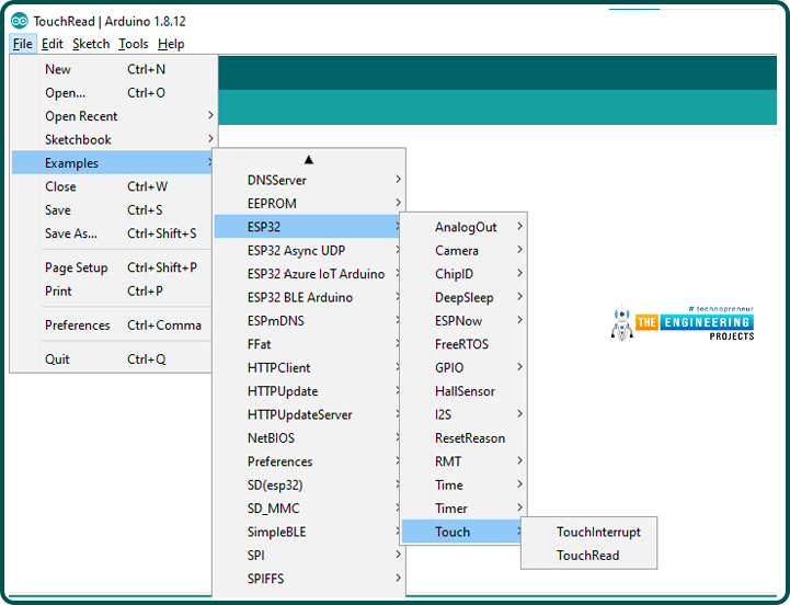
In Arduino IDE there are two example codes available for the ESP32 touch sensor feature. We will discuss and implement both example codes in this tutorial.
Code for ‘touchRead’
// ESP32 Touch Test
void setup()
{
Serial.begin(115200);
delay(1000); // give me time to bring up serial monitor
Serial.println(“ESP32 Touch Test”);
}
void loop()
{
Serial.println(touchRead(T0)); // get value using T0
delay(1000);
}
Code Description
- This is a basic code to test or understand the touch sensor feature of ESP32. Where we are using a touch-sensitive pin to read the variation in capacitance and print the respective readings on the serial monitor.
Setup()
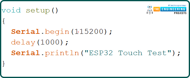
Inside the setup() function, the serial monitor is initialized with a baud rate of 115200 to display the sensor readings.
Loop()
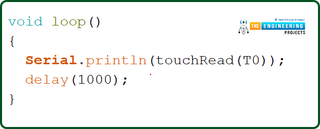
- Inside the loop function the touchRead(T0) function which is using T0 capacitive sensor pin as an argument, is used to continuously read the output of T0 or GPIO pin 4.
- The observed output is continuously printed on the serial monitor with a delay of 1sec.
Testing
- Upload the above code into the ESP32 development board and connect a jumper wire to T0 capacitive sensor pin or GPIO 4.
- To open the serial monitor on Arduino IDE go to Tools > Serial monitor or use Ctrl+Shift+M shortcut key to open the serial monitor.
- Select 115200 baud rate on the serial monitor.
- Observe the output of the T0 pin on the serial monitor
- Now hold the metal end of the jumper wire connected to the GPIO pin 4.

- Now you will see the output of the sensor pin is decreasing.
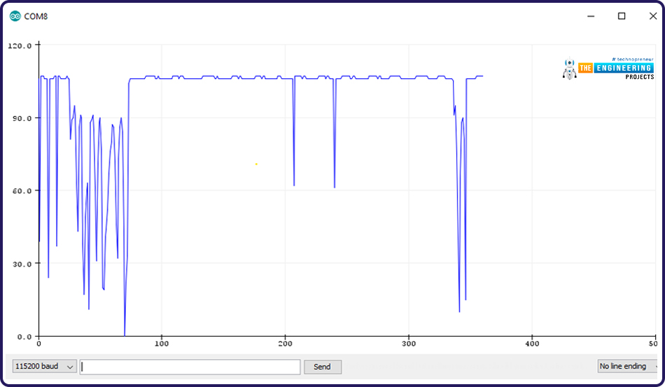
- You can also use the serial plotter to see the results. To open the serial plotter go to Toole > Serial Plotter or use Ctrl+Shift+L shortcut keys.
- Images are attached below from the serial monitor and serial plotter.
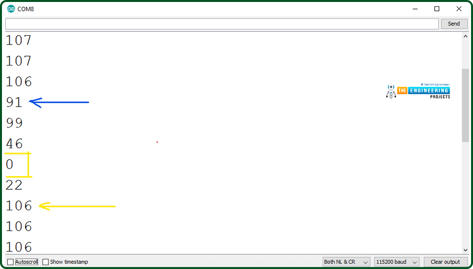
- On the serial monitor and serial plotter, you can see the variation in the sensor reading.
- When we are not touching the sensor pin, the normal sensor output is approximately 107.
- On the other hand, when a body containing electric charge touches a capacitive sensor pin the sensor output value decreases.
Generate Interrupt using Capacitive Touch Pin of ESP32
These capacitive touch sensor pins can also be used to generate an external interrupt for waking up ESP32 from low power modes or to control some peripheral like LED blinking or tuning on a dc motor when a capacitive touch-Interrupt is observed.
Arduino Code
const int CAPACITIVE_TOUCH_INPUT_PIN = T0; // GPIO pin 4
const int LED_OUTPUT_PIN = LED_BUILTIN;
const int TOUCH_THRESHOLD = 40; // turn on light if touchRead value < this threshold
volatile boolean _touchDetected = false;
void setup() {
Serial.begin(115200);
pinMode(LED_OUTPUT_PIN, OUTPUT);
pinMode(LED_OUTPUT_PIN, LOW);
touchAttachInterrupt(CAPACITIVE_TOUCH_INPUT_PIN,
touchDetected, TOUCH_THRESHOLD);
}
void touchDetected()
{
_touchDetected = true;
}
void loop()
{
if(_touchDetected)
{
Serial.println(“Touch detected.”);
_touchDetected = false;
Serial.println(“blink the LED”);
digitalWrite(LED_OUTPUT_PIN, HIGH);
delay(1000);
digitalWrite(LED_OUTPUT_PIN, LOW);
delay(1000);
}
}
Code Description
- The first step is to select the GPIO or touch sensor input pin to trigger an interrupt. We are using T0 or GPIO 4 as an interrupt pin.
- Select the LED output pin which will react or blink on the occurrence of an interrupt.
- In the code, we are using the threshold value of 40. When a body, containing an electric charge touches a touch-sensitive pin, the threshold value decreases below 40.
- The default state of the touchDetect variable is set to false.

Setup()
- Initialize the serial monitor with a baud rate of 115200 so that you can display the results on the serial monitor for debugging purposes.
- Set the LED pin as output and then set the default state to low.
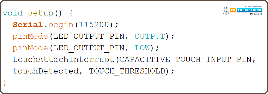
- Attach the interrupt with the capacitive touch pin T0 using touchAttachInterrupt() which is passing the T0 pin, touchdetected() and threshold value as arguments.
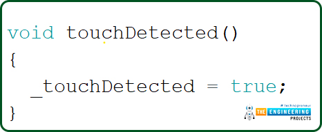
- touchDetected() function will be called when an interrupt is triggered or the state of variable ‘_touchDetected’ is changed to true.
Loop()
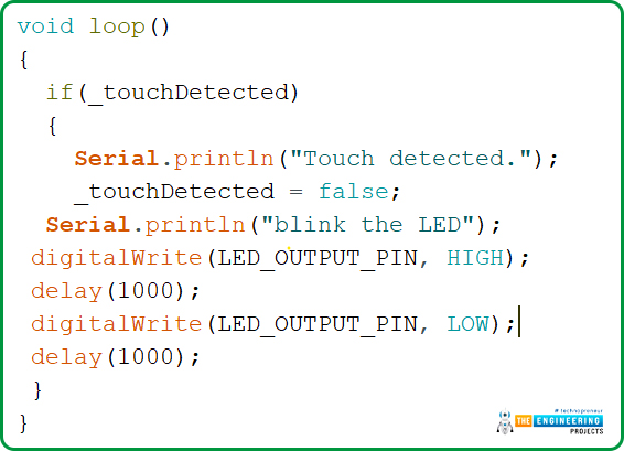
- Inside the loop() function we are using the ‘if’ statement which is continuously checking the state of variable _touchDetected.
- Once the variable state is changed to true or an interrupt is triggered the output LED (inbuilt LED) will start blinking with a delay of 1second.
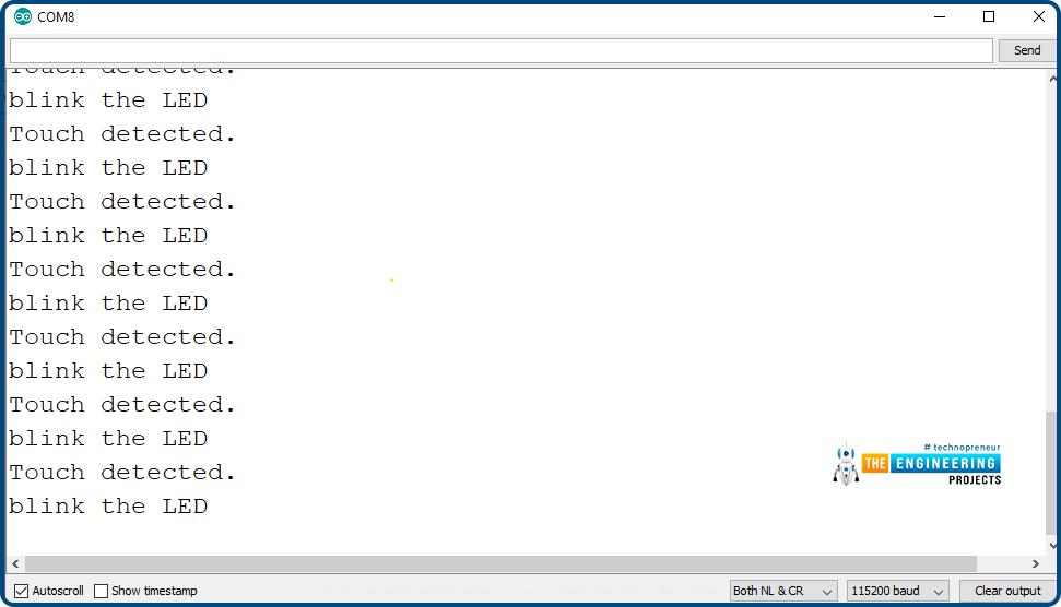
- The respective results will be printed on the serial monitor.
Testing of ESP32 Touch Sensitive Pin
- Open the serial monitor with a 115200 baud rate.
- Connect a male to female jumper wire with T0 or GPIO 4 of ESP32.
- Hold the metallic end of the jumper wire.
- LED will blink with a delay of 1 sec.
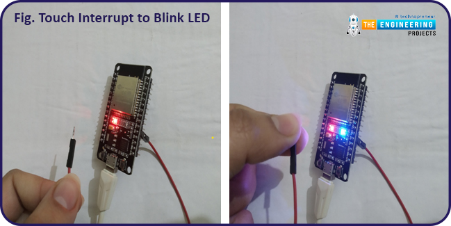
- See the results displayed on the serial monitor.
This concludes the tutorial; I hope you found this helpful and also hope to see you again with a new tutorial on ESP32.
JLCPCB – Prototype 10 PCBs for $2 (For Any Color)
China’s Largest PCB Prototype Enterprise, 600,000+ Customers & 10,000+ Online Orders Daily
How to Get PCB Cash Coupon from JLCPCB: https://bit.ly/2GMCH9w
The post ESP32 Capacitive Touch Sensor appeared first on The Engineering Projects.

No comments:
Post a Comment