 Hello friends, I hope you all are doing great. In today’s tutorial, we are going to share a new Sound Detector Library for Proteus. It’s actually the second version of our previous library Sound Sensor Library for Proteus. We have changed the name as “Sound Detector” is written on these sensors. Moreover, this new sensor is quite small-sized, compact and also has an analog output pin.
We were receiving many complaints about the large size of the previous sound sensor, as it occupies more space and there’s less space left for other components. So, this new one is quite small-sized and I am hopeful students will find it helpful. So, let’s first have a look at What is Sound Detector Sensor and why is it used?
What is Sound Detector Sensor???
- Sound Detector sensor is an Embedded sensor, used for the detection of sound in the surroundings.
- It has both analog & digital outputs and thus gives us information about the intensity of sound as well i.e. how low or high the sound is?
- So these sensors are used for sound detection but they are not used for sound recognition.
Now let’s download the Proteus Library of Sound Detector Sensor and simulate it:
Sound Detector Library for Proteus V2.0
- First of all, download the proteus library of Sound Detector Sensor by clicking the below button:
[DownloadButton title=”Download Proteus Library Files”]
- You will get a zip file of Proteus Library, extract these files and open the folder named “Proteus Library Files”.
- In this folder, you will find three files, titled:
- SoundDetector2TEP.IDX
- SoundDetector2TEP.LIB
- SoundDetector2TEP.HEX
- We need to place these three library files in the Proteus Library folder.
Note:
- If you are facing problems with adding a library in Proteus 7 or 8 Professional, then have a look at How to add a new Library in Proteus 8 Professional.
- Once added the Library files, now open your Proteus software or restart it. (In order to index the library components, proteus has to restart)
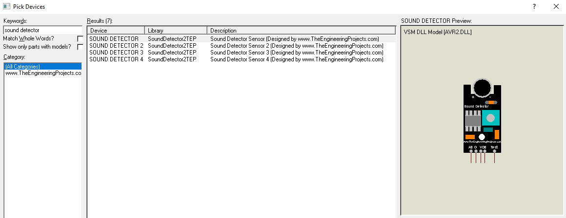
- In the components section, make a search for sound detector and you will get 4 results, shown in the below figure:
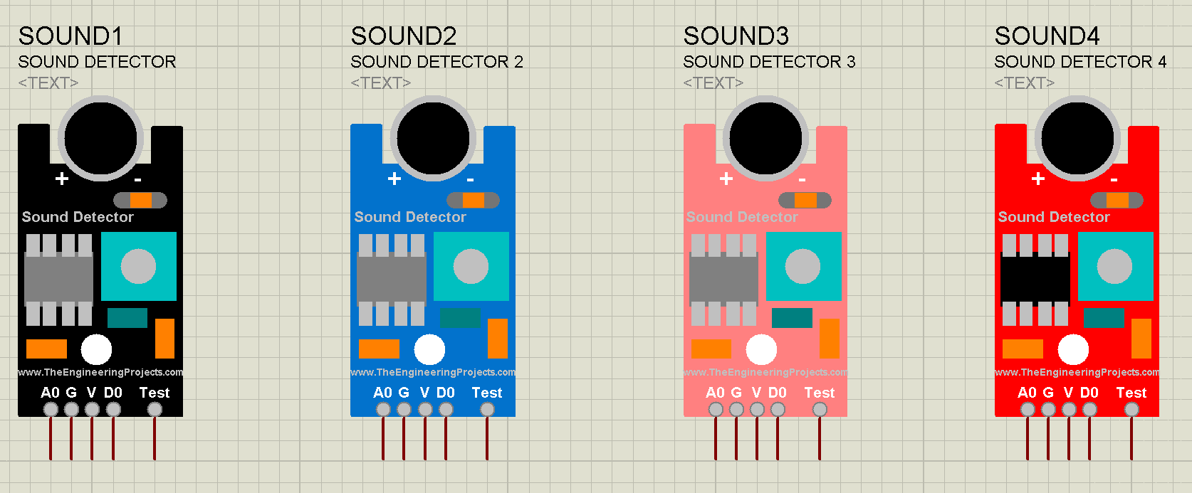
- Now, let’s place all these sensors in the Proteus workspace:
Adding Hex File to the Sensor
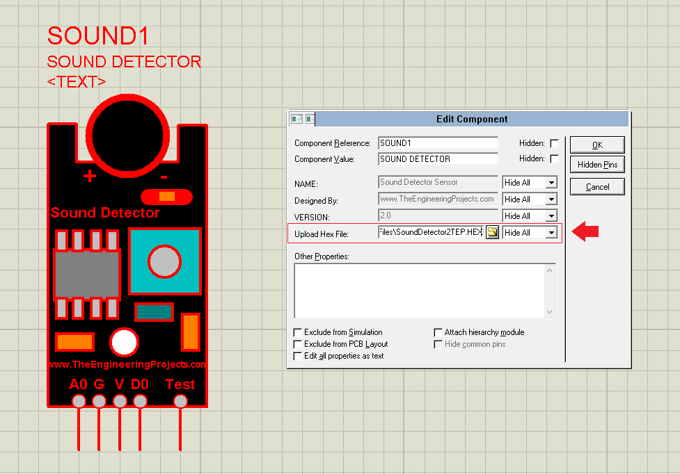
- In order to simulate this sensor in Proteus, we need to add a hex file to the sensor.
- So, double click on the sensor or right-click on it and then click on Edit Properties and it will open up the Properties Panel.
- In the Properties panel, we have a textbox titled Upload Hex File and here we need to add the hex file, which we have placed in the library folder of Proteus, as shown in the below figure:
Now our sensor is ready to simulate, so let’s design a simple circuit to understand its working:
Sound Detector Simulation in Proteus
- As we have seen this sensor consists of 5 pins in total, which are:
- V: Vcc (Power).
- G: Ground.
- D0: Digital Output.
- A0: Analog Output.
- Test: For Testing Purposes. (It’s not present in real sensor)
Why Test Pin is used?
- As we can’t add a real mic in Proteus simulation, so in order to simulate this sensor, we have placed this Test Pin.
- So, when the voltage at Test Pin will increase, the sensor will consider it as sound intensity is increasing.
- We need to connect a potentiometer with this Test Pin.
Sound Detector Circuit Diagram
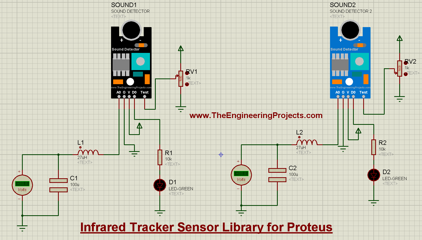
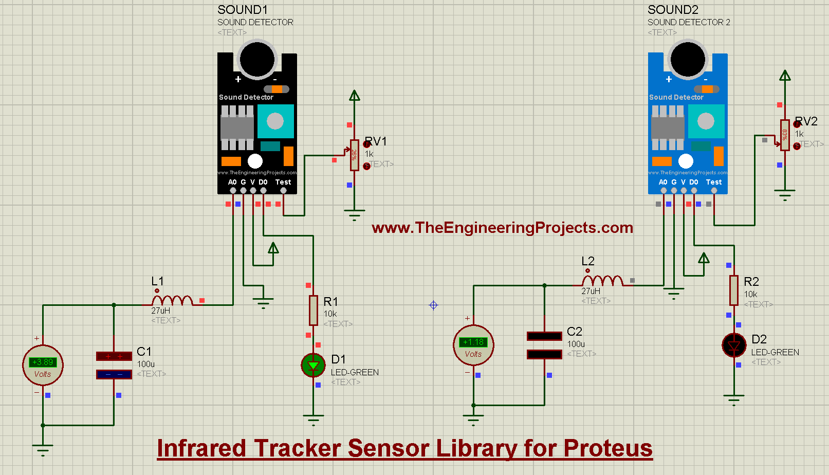
- Now, we need to design a simple circuit in Proteus, as shown in the below figure:
- As you can see in the above figure, I have placed an LC filter on the analog output, because we are getting peak to peak voltage and we need to convert it to Vrms.
- We don’t need to place this LC filter with the real sensor.
- Now, let’s run this simulation and if everything’s good, you will get results as shown in the below figure:
- I have simulated two of these sound detector sensors and you can see they have different outputs because they have different voltage at their Test Pins.
So, that was all for today. If you have any problem in simulating the sound detector, ask in the below comments. We will soon share its simulation with Microcontrollers. Thanks for reading. Take care !!! 
JLCPCB – Prototype 10 PCBs for $2 (For Any Color)
China’s Largest PCB Prototype Enterprise, 600,000+ Customers & 10,000+ Online Orders Daily
How to Get PCB Cash Coupon from JLCPCB: https://bit.ly/2GMCH9w
The post Sound Detector Library for Proteus V2.0 appeared first on The Engineering Projects.
No comments:
Post a Comment