Introduction
Outdoor applications that use solar panels in the range of a few watts often use a microcontroller-based MPPT (Maximum Power Point Tracking) function to extract the maximum power available over the full range of environmental operating conditions. Many microcontroller-based MPPT solutions designed for 20W to 500W consume around 20-100mW of power while continuously dithering the operating voltage of the solar panel to carefully track the maximum PowerPoint. For 20W to 500W panels, this proven technique works well since the energy consumed by the MPPT circuitry is insignificant compared to the additional energy harvested by an effective MPPT algorithm.
However, for an application using a 1W panel, there may only be 100mW available from the solar panel for a significant portion of the winter months or for a significant portion of installations. Applications like this stand to benefit significantly from a solar battery charger that requires far less quiescent current to operate the panel at the maximum power point. One example might be a solar powered sensor that can report more frequently or can now operate for longer periods without battery replacement. Another example would be commercial solar powered lighting that can now operate under much more adverse lighting conditions or with reduced panel sizes.
The LT8611 42V, 2.5A Synchronous Step-Down Regulator with Current Sense and 2.5μA Quiescent Current offers very high efficiency power conversion over an extraordinarily wide range of charging currents which is critical for many solar powered battery chargers which are opportunistic by nature. The LT8611 has both output voltage and output current regulation loops that can be used to provide the CC and CV features in a battery charger. This article explains how the LT8611 can be used with AD5245 digital potentiometer and an external microcontroller to design a micropower solar MPPT battery charger that maintains high efficiency under all panel conditions from low light conditions to full sun for charge currents up to 2.5A. Software development is neccessary to implement this solution. It is assumed that the reader would like to develop or adapt their own MPPT algorithm to run on an external microcontroller.
The terms MPPT and MPPC used in this article have been previously discussed in the following articles:
MPPC (Battey Voltage Dependent)
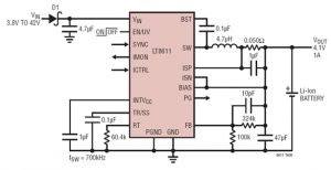
To begin discussing how to enable the MPPT function with the LT8611, let’s start with the 4.1V/1A CCCV Li-Ion battery charger example circuit in the LT8611 datasheet:
Figure 1. LT8611 CCCV Battery Charger
As an example, consider what occurs when a well-lit 1W solar panel that has an Vmp of 9V is connected to this circuit and a Li-Ion battery that rests at 3.8V. When enabled, The LT8611 will attempt to bring the output voltage up to 4.1V at up to a max of 1A. Since the 1W panel cannot provide this power level, the panel voltage will be dragged down below the Vmp of the panel to just above the battery voltage plus the VF of diode D1.
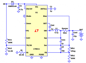
Input voltage regulation will be added to this circuit so that the LT8611 will reduce the battery charge current and maintain the solar panel operating voltage at its maximum power point. As a first step, consider what happens when we add a resistor divider from the input voltage and feed the mid-point to the TR/SS pin of the LT8611 as shown below:
Figure 2. LT8611 CCCV Battery Charger with Input Voltage Regulation
The LT8611’s output error amplifier has an internal 970mV reference and the output divider ratio of this circuit is sized such that the FB pin will reach 970mV when the battery reaches 4.1V. When the battery voltage is 3.8V, the voltage on the FB pin will be 900mV due to the output voltage divider. The LT8611’s tracking feature works such that if the TR/SS pin is driven to less than 970mV, the FB pin will be regulated to a voltage equal to the TR/SS voltage. If this input resistor divider ratio is sized such that the TR/SS is at 900mV when the panel voltage is at its maximum power point of 9V, the LT8611 tracking function will reduce the output voltage (and therefore the battery charge current) to maintain an input voltage of 9V when the battery is at 3.8V. At this point, the circuit has an input regulation or MPPC loop that is battery voltage dependent which is not very useful. For a microcontroller to run a solar panel MPPT scan, it must have control over the input regulation voltage.
MPPT
Adjustment of the input voltage can be implemented in a similar fashion to adjusting the output of a voltage regulator. This is often accomplished by using a control voltage and series resistor connected to the error amplifier input – the TR/SS pin in this case. The control voltage can also be implemented using a filtered PWM output from a microcontroller or a DAC. PWM or DAC options may offer hardware simplicity and lowest cost since these features are typically included in many microcontrollers.
However, these functions are not typically available in the microcontroller’s lowest power state and commonly consume around 1mW. If 1mW of power loss is not significant to the application, this may be the most appropriate technique as PWM control has proven to work reasonably well in this circuit. To save the 1mW of power loss and reduce the time required to scan the solar panel operating range, a digital potentiometer can be used.
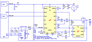
The AD5245 256 Position I2C Compatible Digital Potentiometer draws just a few micro amps from its VDD supply and is available in values up to 100kΩ. If we size the top resistor in the input divider to 309kΩ and use the AD5245 in rheostat configuration along with a series 6.2kΩ resistor in the bottom divider, we can to adjust the input voltage regulation target from 4.5V to 40V via I2C while consuming very little additional power (see Figure 3 below). Once the AD5245 is programmed to operate the panel at its maximum power point, the microcontroller can enter a low power sleep mode. There is no additional current draw other than the microcontroller’s sleep current which is typically under 10µA.
To run an MPPT scan, the AD5245 code is stepped from high resistance to low resistance to operate the panel from the open circuit voltage down to 4.5V while the LT8611’s IMON output is monitored by an ADC to track battery charge current. The AD5245 code that resulted in a maximum battery charge current is used as the maximum operating point of the combined solar panel and charging circuit. Once the AD5245 code is set to operate the panel at its maximum power point, the microcontroller will enter a low power state.
Let’s consider what happens in between MPPT scans which are often scheduled to run at 15 minute intervals. For relatively fast changes in solar irradiance like passing cloud cover, there is no microcontroller involvement. The input voltage divider and LT8611 tracking function will continue to operate the panel at its maximum power point while battery charge current will vary with solar irradiance.
All batteries have some small internal impedance and there will be some small impedance between the battery charger and the battery. This combined impedance is typically less than 100mΩ but will cause slight changes in the LT8611 output voltage during passing cloud cover due to the corresponding changes in battery charge current. These changes in battery voltage are reflected at the LT8611 FB pin. Since LT8611 tracking function will regulate the FB pin to the same voltage as the TR/SS pin, the solar panel operating voltage will increase slightly with solar irradiance. This tends to benefit the MPP tracking effectiveness since solar panel maximum power point voltage increases slightly with increasing solar irradiance.
Over longer periods of time, the battery will charge. If the AD5245 code is not updated, the corresponding increase in battery voltage will increase the voltage that the solar panel is regulated to. The microprocessor will need to run MPPT scans at regular intervals and adjust the AD5245 accordingly to maintain optimal panel voltage while the battery charges.
The complete schematic of the microcontroller, LT8611, AD5245 and LTC4412 is provided below:
Figure 3. MCU Controlled LT8611 MPPT Solar Battery Charger
A 2.6V clamp is used to protect the LT8611 TR/SS pin which has a 4V ABS MAX rating keep the AD5245 wiper pin below its VDD pin which is powered by the battery. The VF drop of D1 in Figure 2 is eliminated by using our LTC4412 Low Loss PowerPath Controller in ThinSOT as an ideal diode controller. By using the LTC4412 on the output of the LT8611, battery drain is minimized when there is no solar power available.
Some implementation details are intentionally omitted here to keep the above schematic simplified and the discussion relatively short. However, there can be some further enhancements for some applications. For instance, it can be helpful to drive the LT8611 SYNC pin high or low with the MCU to keep the IMON output active over the full output current range during an MPPT scan and switching it back after the scan is complete to maintain highest efficiency. Further, this circuit is capable of operating panels at very low power levels. At very low power levels, it is difficult to measure a peak in the IMON output as the panel scan is run. In this case, it is often most beneficial to employ an MPPT algorithm that reads both the panel voltage and the IMON output during an MPPT scan. If the IMON output peak is not found, then the MCU can set the AD5245 code to the value that operates the solar panel at a voltage that is some predetermined ratio of the open circuit panel voltage. This last technique is not uncommon and can be very effective in low power MPPT algorithms.
Conclusion
Under very low power scenarios, it is beneficial to increase the MPPT scan interval since performing an MPPT scan energy. To determine if an MPPT scan is worth running, it may be helpful to not only know the real time charge current but also track how much charge was accumulated since the last scan. Our LTC2942 Battery Gas Gauge with Temperature, Voltage Measurement can be used to track accumulated charge via I2C and determine algorithm effectiveness. It also enables the MCU to dynamically balance power consumption with accumulated charge. The LTC2942 is an accurate and very low power gas gauge which consumes only 70uA while accumulating charge. The LTC2942 also has a shutdown mode that can be used when not in use. For higher battery voltages, our LTC2943 Multicell Battery Gas Gauge with Temperature, Voltage and Current Measurement and LTC2944 60V Battery Gas Gauge with Temperature, Voltage and Current Measurement can be used. For higher charge currents, our LT8613 42V Synchronous Step-Down Regulator with Current Sense and 3μA Quiescent Current can be used at up to 6A.

The post High Efficiency Solar MPPT Battery Charger Using LT8611 and AD5245 appeared first on ELE Times.


No comments:
Post a Comment