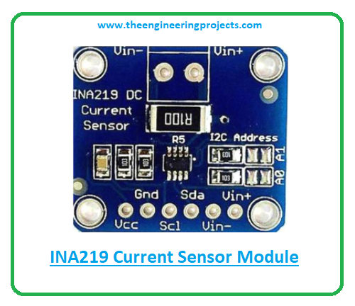
 Hi Friends! Hope you’re well today. I welcome you on board. In this post today, I’ll walk you through the Introduction to INA219.
The INA219 is a current sensor module that incorporates I2C protocol for submitting the data obtained through sensing current, voltage, and power. It is a bi-directional zero drift current/ power sensing module mainly used in digital multimeter and power profiler.
I suggest you read this post all the way through as I’ll detail the complete Introduction to INA219 covering datasheet, pinout, features, and applications.
Let’s get started.
Introduction to INA219
- INA219 is a current/power sensor module mainly employed to sense the power, voltage or current where up to 128 samples can be averaged together to get filtering in noisy environments. This data is then submitted to a microcontroller using the I2C bus.
- This device features an I2C protocol mainly used to transmit data between devices. The I2C protocol comes with two wires SDA and SCL. The SDL is a serial data line that carries the data while SCL is a serial clock line that carries the clock signal and ensures the synchronization of data transfer over an I2C bus.
- In the I2C protocol, one device acts like a master and the other as a slave. Using this communication protocol you can attach multiple slaves with a single master whereas you can also control single or multiple slave devices with multiple masters.
- INA219 can be easily incorporated with the microcontrollers and Arduino boards and with devices that come with an I2C bus interface.
- It also contains 2W 0.1 Ohms 1% rated shunt resistor mainly employed to fulfill the current measuring requirements.
- This sensor module is a key part of the power monitoring systems. And the power input of this device ranges from 3V to 5.5V and the target voltage is up to +26V.
INA219 Datasheet
It is better to go through the datasheet of the device before you embed this device into your electrical project. The datasheet features the main characteristics of the module. Click the link below to download the datasheet of INA219.
INA219 Pinout
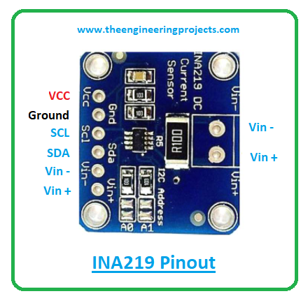
The following figure shows the pinout diagram of INA219.
The following table represents the pin description of each pin incorporated into the module.
| Pin Description of INA219 | ||||
|---|---|---|---|---|
| Pin No. | Pin Description | Pin Name | ||
| 1 | Sensed Input line – | VIN- | ||
| 2 | Sensed Input line + | VIN+ | ||
| 3 | Input voltage | VCC | ||
| 4 | Connected to ground | GND | ||
| 5 | Serial clock line that carries the clock signal | SCL | ||
| 6 | Serial data line that contains the data | SDA | ||
INA219 Features
- Contains 2C- or SMBus-compatible interface
- Comes with up to +26V target voltage
- Power Input Range = 3.0V-5.5V
- Can Sense Bus Voltages ranging from 0 to 26 V
- Up to 128 samples are averaged to get filtering in noisy environments.
- Capable of up to ±3.2A current measurement, with ±0.8mA resolution
- Contains ohm 1% 2W current sense resistor
- Board Dimension = 0.8 x 0.9 inch (l x w x h)
INA219 Applications
- Used in power monitoring systems
- Employed in power profiler
- Used in digital multimeter
That’s all for today. Hope you find this article helpful. If you’re unsure or have any questions, you can approach me in the section below. I’d love to help you the best way I can. Feel free to share your valuable feedback and suggestions around the content we share so we keep coming back with quality content customized to your exact needs and requirements. Thank you for reading the article.
JLCPCB – Prototype 10 PCBs for $2 (For Any Color)
China’s Largest PCB Prototype Enterprise, 600,000+ Customers & 10,000+ Online Orders Daily
How to Get PCB Cash Coupon from JLCPCB: https://bit.ly/2GMCH9w
The post INA219 Current Sensor Module Datasheet, Pinout, Features & Applications appeared first on The Engineering Projects.


No comments:
Post a Comment