
 Hi Friends! I welcome you on board. Happy to see you around. In this post today, I’ll walk you through the Introduction to Arduino Pico.
The Arduino Pico is the world’s smallest Arduino compatible board. The smallest feature makes it a good fit for the disposable student project. These boards consume so little energy that even a small battery is enough to provide them decent power and put them in a running position. At the time of writing this article, Arduino Pico is priced at 18$ which is less than the price of other Arduino boards.
Arduino boards are introduced in modern electronics to make projects economical and lightweight that don’t involve a lot of technical expertise and even a common man with no prior knowledge about programming what so ever can get hands-on experience with them. This smallest Pico version is readily available to turn your innovative thoughts into reality.
I suggest you read this post all the way through as I’ll detail the complete Introduction to Arduino Pico covering datasheet, pinout, features, pin description, programming and communication and applications.
Let’s get started.
Introduction to Arduino Pico
- Developed by MellBell Electronics (the Canadian-based hardware and electronics company), Arduino Pico is the world’s smallest Arduino development board.
- The module is based on an Atmega32u4 microcontroller which is a 44 pin small chip compatible with Arduino Leonardo.
- This tiny beast may look small, but it is capable of performing functions like common Arduino boards. The small size of around 0.6”x0.6” and 1.1g weight is what makes it special for a range of applications.
- This device features 8 digital I/O pins, 3 analog pins, and 1 PWM channel.
- Moreover, the board operates at 5V while the input voltage ranges from 7V to 12V.
- The board contains one micro USP port, a reset button, and several I/O pins that operate at 40mA.
- This module features a crystal oscillator frequency up to 16 MHz that is mainly used to create clock pulses with a decent pace. This frequency is required for the synchronization of all the internal operations.
- The flash memory is 32KB out of which 4KB is used by Bootloader. It is the memory where the sketch is stored. (The code we compile on Arduino IDE software is called a sketch)
- The Bootloader is the little program that starts running when you turn on the Arduino or hit the reset button. The main purpose of this Bootloader is to create a delay in sending a new code for the Arduino from the Arduino IDE software running on your system, which is then written on the Arduino memory.
- The SRAM memory is 2.5KB which is volatile memory and is mainly used to produce and manipulate variables when it starts running.
- In addition, Mellbell offers an aluminum version of the board that can easily accommodate in overheated environments and applications.
Arduino Pico Datasheet
Before you apply this device to your electrical project, it’s wise to scan through the datasheet of the device that features the main characteristics of the board. You can download the datasheet of Arduino Pico by clicking the link below.
Arduino Pico Features
The following are the main features of the Arduino Pico board.
- Based on the ATmega32u4 microcontroller,
- Runs at a clocked frequency of 16 MHz
- 40 mA DC current per I/O pin
- 5 kB of SRAM memory
- Bootloader = Leonardo compatible
- Reset enable = 1 pin
- 3 SPI enabled pads on the back of the board
- 32 kB of internal Flash (4 kB used by the bootloader)
- 8x digital I/O pins, 1x PWM channel, and 3x analog input channels.
- The operating voltage is 5V.
- Input voltage range = 7 to 12 V.
- 6 x 0.6 inches size. Weight of 1.1 grams
- Bootloader compatible with the Arduino Leonardo
Arduino Pico Pin Description
- Hope you’ve got the sneak peek of this smallest Arduino board. In this section, we’ll detail the pin description of the pins installed on the board.
Analog Pins
- There are 3 analog pins available on the board. These pins can get any number of values in opposed to digital pins which get only two values i.e. HIGH and LOW.
PWM Pins
- This board incorporates one PWM channel which is employed to receive some of the analog output’s functions. When the PWM is activated, the board generates analog results with digital means.
Digital Pins
- Total 8 digital pins are employed on the board. These pins are introduced to be configured as inputs or outputs according to the requirement. These pins remain ON or OFF. When they are in the OFF state they are in a LOW voltage state receiving 0V and they are in HIGH voltage state they receive 5V.
Atmega32u4 Pinout
- The following figure represents the pinout diagram of Atmega32u4.
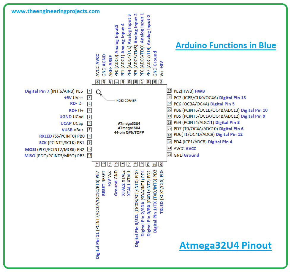
Atmega32u4 Pin Description
- In this section, we’ll detail the pin description of each pin available on Atmega32u4.
Vcc
- Digital voltage supply pin.
GND
- Ground Pin.
Port B (PB7…PB0)
- Port B is attached with pull-up resistors and is an 8-bit bidirectional I/O port. The pull up resistors are mainly employed to limit the current. This port is more efficient and contains better driving capabilities compared to other ports.
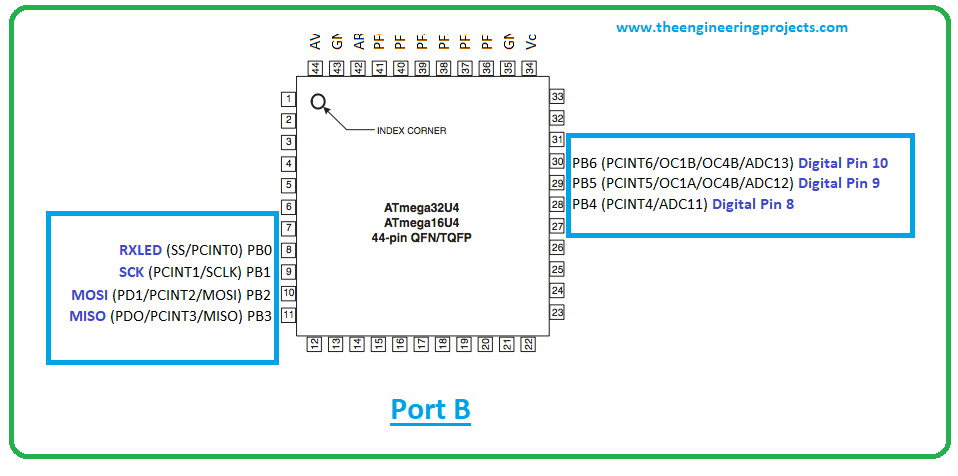
- When the pull up resistors are activated in this port C, it will source current with port pins extremely pulled low.
Port C (PC6, PC7)
- Port C is an 8-bit bidirectional I/O port that contains pull-up resistors.
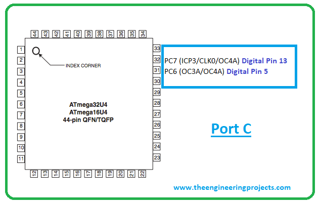
- When the pull up resistors are activated, Port C is used to source current with port pins extremely pulled low – Similar to Port B.
Port D (PD7..PD0)
- Port D is a bi-directional 8-bit I/O port with pull-up resistors. When the reset condition is activated, the Port D pins are tri-stated.

Port E (PE6, PE2)
- Only two bits PE6 and PE2 are available on the product pinout. It is an 8-bit bidirectional port that features internal pull up resistors to limit the current.
Port F (PF7..PF4, PF1,PF0)
- Port F is a bidirectional port that serves as analog inputs for the A/D converter. Two bits PF2 and PF3 are not available on the device pinout.

D+
- USB Full speed / Low Speed Positive Data Upstream Port. It is connected to the USB D+ connector pin employed with the serial resistor 22W.
D-
- USB Full speed / Low Speed Negative Data Upstream Port. It must be connected to the USB D- connector pin incorporated with serial resistor 22W.
UGND
- This is USB pads ground.
UCAP
- USB Pads Internal Regulator Output supply voltage.
UVCC
- USB Pads internal regulator Input supply voltage.
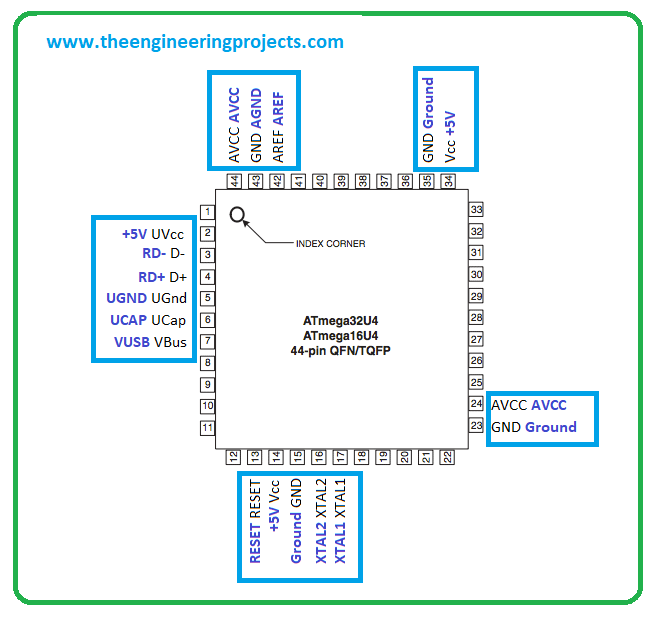
VBUS
It is USB VBUS monitor input.
XTAL1
- Input to the inverting Oscillator amplifier and Input to the internal clock operating circuit.
XTAL2
- Output from the inverting Oscillator amplifier.
RESET
- A reset pin. When a low level applied to this pin for a longer period of time, it produces a reset. It is important to note that shorter pulses may not generate a reset.
AVCC
- AVCC is the supply voltage pin for all the A/D Converter channels.
AREF
- This pin is utilized as the analog reference pin for the A/D Converter.
Communication and Programming
- The module comes with different communication protocols including I2C, and UART.
- The UART is a serial communication protocol that carries two lines Tx and Rx where the former is a transmission line used to transfer the serial data and the latter is a receive data line used to receive the serial data.
- The I2C is a two-wire communication protocol that contains two lines named SCL and SDA. The SCL is a serial clock line that is used for the synchronization of all data transfer over the I2C bus while SDA is a serial data line mainly used to carry the data.
- Arduino IDE is the professional software developed by Arduino.cc that is used to program all types of Arduino Boards.
- Connect the board through USB to the computer and test and program the board as you like better.
Arduino Pico Applications
- Creating a wireless keyboard
- Water level meter.
- Health and security systems
- Student projects
- Embedded systems
- Industrial automation
- Automatic pill dispenser
It is important to note that all Arduino boards are microcontrollers but not all microcontrollers are Arduino boards. Due to its small size and easy to use functions, most people prefer Arduino boards over microcontrollers. Moreover, you don’t need to include extra peripherals while using these boards, as they come with built-in functions that don’t require the addition of external components.
That’s all for today. I hope you’ve enjoyed reading this article. If you’re unsure or have any questions, you can approach me in the section below. I’d love to help you the best way I can. You’re most welcome to share your valuable feedback and suggestions around the content we share so we keep sharing quality content customized to your exact needs and requirements. Thank you for reading the article.
JLCPCB – Prototype 10 PCBs for $2 (For Any Color)
China’s Largest PCB Prototype Enterprise, 600,000+ Customers & 10,000+ Online Orders Daily
How to Get PCB Cash Coupon from JLCPCB: https://bit.ly/2GMCH9w
The post Introduction to Arduino Pico appeared first on The Engineering Projects.
No comments:
Post a Comment