
The two inputs of Latches are called “S” and “R” where S stands for SET and R stands for RESET. Due to inputs , latches can have four unique combinations of the input. The output is denoted as “Q” and is totally dependent on the input Combination.
Nevertheless, another Output is also used in the circuit sometimes. this output is denoted as Q’ and is read as Q bar, Complement of Q or bar Q NOT Q because it is also written as ![]()
One can have an idea that this output is the invert result of “Q” output and depends on the Q and successively to the inputs S and R.
Two types of circuits are possible in latches:
- Active high circuits.
- Active low circuits.
Both of them are same in the Components but are different due to the arrangement of the Components.
Active high circuits: In this kind of the Circuit the inputs are grounded and therefore are LOW .Latch are triggered momentary high signal.
Active Low Circuits: In this kind the inputs are LOW and the latches are triggered at high signals.
TYPES OF LATCHES
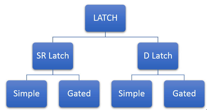
- SR Latches
- D Latches.
whereas, 1st two types are further subdivided into two categories:
- Simple
- Gated
All of theses types along with the implementations are shown in figure on right side.
Prior to start DO YOU KNOW???????
- Logic Probes are used to give input to the circuit. They can only give two types of inputs:
- High ( Denoted by 1)
- Low ( Denoted by 0)
- By the same token, Logic toggle show the output. There are two types of output:
- High ( Denoted by 1)
- Low ( Denoted by 0)
- NAND gate shows the output LOW ( or 0) only when both the inputs are HIGH.
- NOT gate show is an inverter gate.
- NOR gate shows the output HIGH ( or 1) only when both the inputs are HIGH.
Implementation of Latches in Proteus ISIS
For best understanding, we’ll design each of the type and create the truth table.
Devices Required:
- AND Gate
- NOT Gate
- Three input AND Gate
- Logic Toggle
- Logic Probe
- Clock
Procedure:
All the Circuits follow almost same procedure. Even so, they are different in the Construction and the characteristics.
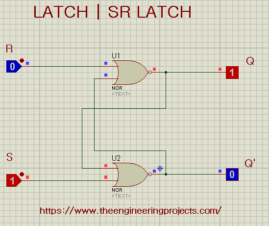
1. SR Latches in Proteus ISIS
- Choose Two NOR Gates and fix them on the working area.
- Examine the Circuit diagram and arrange the other required Components according to the Circuit diagram.
- Truss all the Components by wires with the help of circuit diagram.
- Pop the Play button and fill the truth table.
NOTE: You can also make this Circuit with NAND Gate.
Examination:
The SR latch ( SET/RESET) mainly change according to the change in the S line. that means, whenever the S is HIGH the Q ( output) is shown as HIGH and vise versa. but when both the inputs (SET & RESET) are HIGH then we seen that both the outputs are LOW. Q ( output ) is alway the inverse of Q’.
Once we check all the Conditions we can assemble our own truth table. I have made a truth table that shows us the following result:
| S | R | Q | Q’ |
| 0 | 0 | 0 | 1 |
| 0 | 1 | 1 | 0 |
| 1 | 0 | 0 | 1 |
| 1 | 1 | 0 | 0 |
2. Gated SR Latch in Proteus ISIS
The SR latch are not Complete, hence the performance can be enhanced by the a process called “Gating” , and the resultant circuit is called Gated SR Circuit.
- We add two Positive NOR gates at the input “S” and “R” that have inverted input using NOT Gates. In this way we can examine the Condition more clearly when both the inputs in SR gate were HIGH.
- The circuit works well when we add a clock in the two inputs of the NOR gates.
The Circuit of Gated SR is shown next:
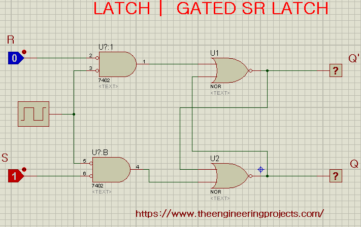
When we test the Circuit’s all conditions , the output have some difference. The output here shows us the difference. During the LOW conditions of the Circuit the output shows us the error or Latch.
| CLK | S | R | Q | Q’ |
| 0 | X | X | LATCH | LATCH |
| 1 | 0 | 0 | LATCH | LATCH |
| 1 | 0 | 1 | 0 | 1 |
| 1 | 1 | 0 | 1 | 0 |
| 1 | 1 | 1 | 1 | 0 |
3. D Latches in Proteus ISIS
D latch is a modification of the Gated SK Latch.
- we add the NOT Gate in advance of the RESET (R) Input and we get the circuit that looks like this:
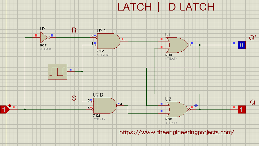
Accordingly to the Picture, the D and clock are now the inputs of the Circuit and we can notice the output at Q and Q’.
| CLK | D | Q | Q’ |
| 0 | 0 | 0 | 1 |
| 0 | 1 | 1 | 0 |
| 1 | 0 | 0 | 1 |
| 1 | 1 | 1 | 0 |
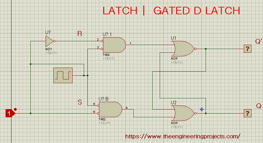
4. Gated D Latch in Proteus ISIS
This is another type of D Latch.
- Connect the clock with the D input so that we alter the D input. But with this change, we see the changes in the output as well.
Let’s have a look on the Circuit of Gated D Latch:
when we change the D and test all the Condition, the resultant truth table is:
| CLK | D | Q | Q’ |
| 0 | 0 | 0 | 1 |
| 0 | 1 | 0 | 1 |
| 1 | 0 | 0 | 1 |
| 1 | 1 | 0 | 1 |
Hence today we learnt about the latches, some basic concepts and its types along with practical implementation.
JLCPCB – Prototype 10 PCBs for $2 (For Any Color)
China’s Largest PCB Prototype Enterprise, 600,000+ Customers & 10,000+ Online Orders Daily
How to Get PCB Cash Coupon from JLCPCB: https://bit.ly/2GMCH9w
The post Digital Latches Implementation in Proteus | SR-Latches | D-Latches appeared first on The Engineering Projects.
No comments:
Post a Comment