
- What are Logic Gates.
- What are the types.
- What are the truth table
- How Gates are Implemented in Proteus ISIS.
Rush towards the 1st Question.
Logic Gates
while Designing the digital system, the Basic building blocks of the system are logic gates. we define the Logic Gates as:
“Logic Gates are the electronic circuits that has one or more input and output and the output depends upon a certain logic used during the designing.”
There are some types of Logic Gates that have some types and every type is used for certain outputs according to need.
Types of Logic Gate
Here, we’ll discuss some basic kinds of the Logic Gates and we’ll discuss them one after the other.
- AND Gate
- OR Gate
- NOT Gate
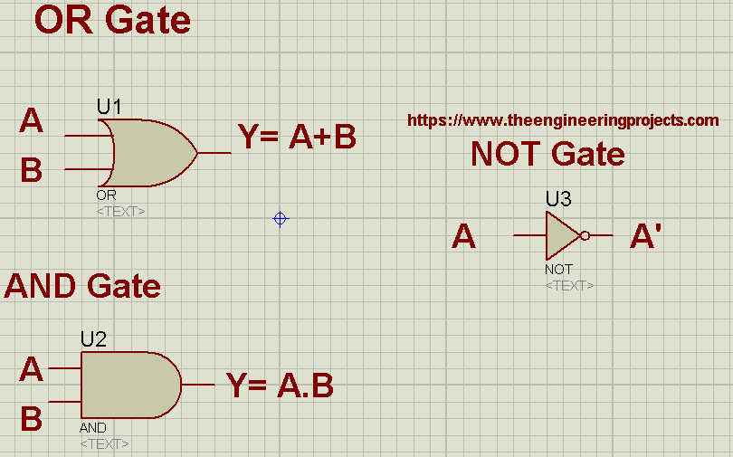
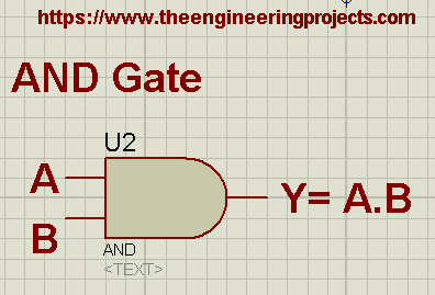
AND gate
The AND Gate Performs the Logical conjunction. We denote it with the Dot between the inputs and define the AND Gate as:
“AND Gate is the Logical gate that has the HIGH output only when both the Inputs are HIGH and LOW in all other Conditions.”
The numbers of Inputs in AND Gate are more than one i.e, >=2 and output is only one. If A , B are the Logic Inputs and Y is the Output then we denote A AND B as A.B=Y. The logical Symbol of AND gate is:
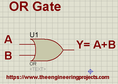
OR Gate
OR gate Performs the Disjunction logic in the Circuit. the symbol of this logic is a plus sign “+”. Identical to AND Gate, OR Gate also has minimum two inputs and one output. If A and B are the inputs and Y is the output of OR Gate then A OR B is denoted by A+B=Y.
“OR Gate is the basic logic gate that has the LOW output only when both of its inputs are low otherwise it has high output.”
The logical Diagram of OR Gate is given next:
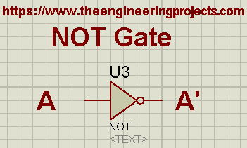
NOT Gate
In Logic Circuits, the NOR Gate performs the inversion. This is unary logic Gate that implies it has only one input and one output. The output of NOT Gate is denoted by a Bar or Complement on the symbol of the input.
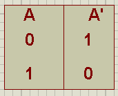
If A is the input to the NOT Gate, then A’ is the output of NOR Gate.
if we look at the logical diagram, then for NOT Gate it is:
Truth Tables
Truth Tables are Logical Tables that are important while designing the Digital Circuit. The elucidation of truth table is given below:
“A truth table is the logical type of table that describes the Input and Output of the system at the same time and the connection between them.”
These are useful in Boolean and mathematical operation as the relationship of the Input and Output can be understood at a glance.
the input conditions of the truth table depends upon the number of input. We decide the number of conditions through 2^n where “n” is the number of the inputs. If we have two input then we will test four conditions and A will be zero at start but changes after two conditions. Whereas, B will start from zero and change its values in every condition.
Execution in Proteus ISIS
For best understanding, I am going to implement these logic Circuits in Proteus ISIS so that we’ll be able to make a truth table for each of the Logic circuit based upon the Practical evidence.
Prior to start, just have a look at some basic Components.
Logic Probes
In the Boolean Circuits, We use Logic toggle that is a Component in Proteus ISIS that are used to see the Output of the Circuit. They are connected through a wire with the output and have the ability to show only two Conditions i.e, either HIGH or Low ( Boolean output).
Logic Toggle
Logic Probes are also the Boolean devices and they are used to give the Input to logic circuits. They just have two conditions and we can switch the input from HIGH to LOW or vise versa through a small arrow presented on one side of the Logic Toggle.
Simulation
For the Simulation of Logic Gates, you have to Grab the following Components from the Pick Library.
Devices required
- AND Gate
- OR Gate
- NOT Gate
- Logic Toggle
- Logic Probe
Procedure
AND Gate
- Take all the Components from Pick Library through “P” button.,
- Set the AND Gate at the Working area.
- Take logic Probe from the Library and set it at the output.
- Take the Logic Toggle and set two toggles on each of the input.
- Pop the Play button.
- Change the Conditions of the Logic toggle one after the other according to the truth table and record the values of output.
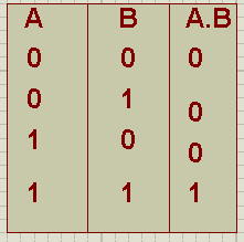
The resultant Truth Table of AND gate should be as following:
OR Gate
- Get the OR gate from the Library.
- Attach Logic Toggles with the Inputs.
- Join the Logic Probe at the output.
- hit the play button.
- Change the values of Logic Toggle according to the values in the truth table.
- Record the output in the result bar.
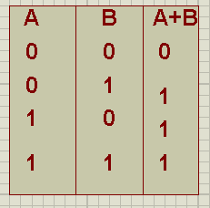
- The resultant truth table of OR gate is:
NOT Gate:
- Grab the NOT Gate from library.
- Attach logic Probe and logic gate at input and output.
- NOT Gate has only one input. Hence give it high and low value one by one.
- Record results.
Truss today we learnt about the basic blocks of logic circuits i.e, logic gates, We learnt about the truth tables and use the logic gates in Proteus simulation. In next tutorials, we’ll use these gates to make other gates and circuits.
JLCPCB – Prototype 10 PCBs for $2 (For Any Color)
China’s Largest PCB Prototype Enterprise, 600,000+ Customers & 10,000+ Online Orders Daily
How to Get PCB Cash Coupon from JLCPCB: https://bit.ly/2GMCH9w
The post Basic Logic Gates in Proteus with Truth Table appeared first on The Engineering Projects.
No comments:
Post a Comment